
NE
Purpose
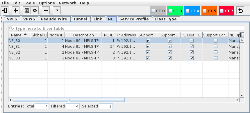
Displays the ENP nodes domain’s member NEs.
Allows you to add/remove NEs to/from the ENP-Nodes domain. Only NEs added to the domain named “ENP-Nodes” will be correctly manageable as MPLS-capable NEs.
Allows you to set/modify the Global ID, Node ID and Description of NEs not yet added to the ENP-Nodes domain. For an NE to be added to the ENP-Nodes domain, the combination of Global ID and Node ID must unique.
Displays the selected NE details, which include the following information:
− MPLS-TP details including the node’s Global/Node ID and Description,
− List of VPLS/VPWS and tunnels in which the NE is involved,
− MPLS-TP interfaces and labels with bandwidth, port, and encryption information,
− List of the NE’s available bridge ports and VLANs.The bridge port is the Port attached to the bridge on the node with type CVP,
− Ethernet packet statistics of ports with PM data collection jobs defined.
Synchronizes the NE’s “Known Network Element” table. This process automatically updates the table with all the NEs of the ENP domain.
The number of selected entries in the NE table is shown in the bottom fields (Entries: Total, Filtered, Selected).
Please note:
To deploy a tunnel, every NE in the path has to know the ingress and egress NEs. These endpoint NEs should be stored in every NE’s “Known Network Element” table, otherwise a tunnel instance on the NE cannot be created.
Dialog image
ENP – NE
ENP – Add NEs to ENP-Nodes Domain
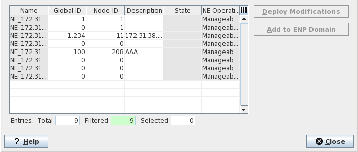
Mandatory entries
Add to ENP Domain
Optional entries
Synchronize NE…
NE Details
Informational content
Name | Configured NE name. |
Global ID Node ID | The pair of Global ID and Node ID should be unique. |
Description | The specified Description of the node. |
NE ID | The NE ID automatically set by the FOXMAN‑UN system. |
Addressing | IP address of the node. |
BW Enforcement | Indicates whether bandwidth enforcement is applied or not. BW enforcement is possible when a HQoS profile has been applied to the link and/or the NEs terminating the link. The following options are possible: - Enabled: all “BW Enforcement” options are enabled on the link; - Disabled: None of the “BW Enforcement” options are enabled on the link; - Partial Enabled: Some of the “BW Enforcement” options are enabled on the link, some aren’t; - Unsupported: HQoS (egress shapers) not supported on the link; - Unknown: Default status (as long as ENP is not synchronized with the NE). |
Support QoS | Indicates whether the node supports QoS / Service Profiles or not. A mark in the checkbox indicates that QoS is supported. Older node software may not support the current QoS implementation. |
Support Encryption | Indicates whether the node supports encryption. A mark in the checkbox indicates that encryption is supported. Older node software may not support encryption. |
PE Dual Home Capable | Indicates whether the NE is Dual Home capable or not. |
Support Egress Shaping | Indicates whether the NE supports the Egress Shaping feature or not. The feature depends on the software version of the NE core unit. |
NE Operational State | The status of the node as defined by the core. |
Alarm State | Shows the highest active alarm severity of the NE. |
Tag | The Tags configured in the NE properties. |
Services Usage | Plenty [of space available] (<90%, green), Little [space available] (≥90%, orange), Full (100%, red), Exceeded (>100%, red), with color indication. |
Tunnels Usage | Plenty [of space available] (<90%, green), Little [space available] (≥90%, orange), Full (100%, red), Exceeded (>100%, red), with color indication. |
VPLS Instances | Current / maximum of Terminated VPLS Instances, with colored bar usage graph (green: <90%; orange: ≥90%; red: ≥100% usage). |
Pseudo Wires | Current / maximum of PWs, with colored bar graph (green: <90%; orange: ≥90%; red: ≥100% usage). |
Tunnels | Current / maximum of Tunnels, with colored bar graph (green: <90%; orange: ≥90%; red: ≥100% usage). |
LSPs | Current / maximum of LSPs, with colored bar graph (green: <90%; orange: ≥90%; red: ≥100% usage). |
Transit LSPs | Current / maximum of Transit LSPs, with colored bar graph (green: <90%; orange: ≥90%; red: ≥100% usage). |
Fast BFD Sessions1 | Used / (used + available), with colored bar graph (green: <90%; orange: ≥90%; red: ≥100% usage). |
Medium BFD Sessions1 | Used / (used + available), with colored bar graph (green: <90%; orange: ≥90%; red: ≥100% usage). |
Slow BFD Sessions1 | Used / (used + available), with colored bar graph (green: <90%; orange: ≥90%; red: ≥100% usage). |
Since slow, medium, and fast BFD sessions share resources, the maximum available number of BFD sessions per type is only valid if no other BFD session types are used. Due to that, the usage number shown in the bar graph for BDF sessions per BFD type (slow, medium, fast) is not calculated as [used / maximum] but as [used / (used + available)]. | |
Software Version | Indicates what SW version is used on the core unit(s). The software version determines some of the features available on the NE. |
Controls (buttons, menu items, etc.)
Edit
Add NEs… | Calls the ENP – Add NEs to ENP-Nodes Domain dialog. | |
NE Details… | Calls the NE Details dialog. | |
Configuration <user class>… | When selected from the context menu of an NE, opens the NE configuration in the FOXCST GUI with the chosen user class. | |
Force Polling | Requests an immediate poll of the NE. This will read the complete NE configuration, inventory, and alarm status information from the selected NE(s). | |
Synchronize NE… |  | Synchronizes the selected NE configuration with the ENP database. Where the ENP database does not have information available about the number of current / maximum instances it is synchronized with the NE / network. |
Remove NEs… | Remove selected NE(s) from ENP-Nodes domain. Note: The saved configuration for the removed node will be lost. This means the VPLS nodes, the LSP and all related MPLS-TP objects are removed from the FOXMAN‑UN database. The deployed configurations on that particular node will not be lost. | |
Switch BW Enforcement | Opens a sub menu to select bandwidth (BW) enforcement. The following options are available: - On (this will only change the shapers which are managed by FOXMAN‑UN and which had BW Enforcement by the profile); - Off (on node level this switch off all CT Shapers and Default Shapers). | |
Basic TE Configuration | Opens one of the Basic TE Configuration functions (see below). | |
Backplane Audit | Opens one of the Backplane Audit functions (see below). |
Tools
Basic TE Configuration functions | ||
Show Network Audit Result… | Calls the “Network Audit Result” dialog. | |
Schedule Network Alignment… | Calls the “Schedule Network Alignment” dialog. | |
Schedule Network Audit… | Calls the “Schedule Network Audit” dialog. | |
Manage Reference Data… | Calls the “Manage QoS Reference Tables” dialog. | |
Backplane Audit functions | ||
Show Backplane Audit Result… | Calls the “Backplane Audit Result” dialog. | |
Schedule Backplane Audit… | Calls the “Schedule Backplane Audit” dialog. | |
NE Details
Opens the NE Details dialog, also see the dialog image below.
Dialog image
NE [name]
? Help | Calls the help viewer and opens this page. |
Exit | Closes the dialog. |
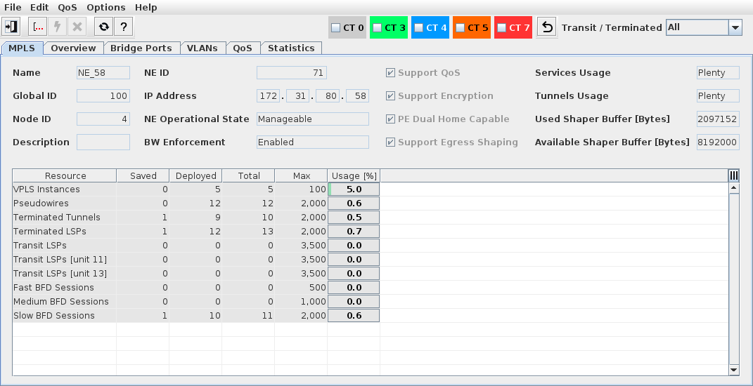
NE Details: MPLS
Name | Configured NE name. |
Global ID Node ID | The pair of Global ID and Node ID should be unique. |
Description | The specified Description of the node. |
NE ID | The NE ID automatically set by the FOXMAN‑UN system. |
Addressing | IP address of the node. |
NE Operational State | The status of the node as defined by the core. |
BW Enforcement | The status of bandwidth enforcement on the node (Unsupported, Disabled, Partial Enabled, Enabled). |
Support QoS | Indicates whether the node supports QoS / Service Profiles or not. A mark in the checkbox indicates that QoS is supported. Older node software may not support the current QoS implementation. |
Support Encryption | Indicates whether the node supports encryption. A mark in the checkbox indicates that encryption is supported. Older node software may not support encryption. |
PE Dual Home Capable | Indicates whether the NE is Dual Home capable or not. |
Support Egress Shaping | When marked, indicates that the NE supports egress shaping. |
Services Usage | Plenty [of space available] (<90%, green), Little [space available] (≥90%, orange), Full (100%, red), Exceeded (>100%, red), with color indication. |
Tunnels Usage | Plenty [of space available] (<90%, green), Little [space available] (≥90%, orange), Full (100%, red), Exceeded (>100%, red), with color indication. |
Used Shaper Buffer [Bytes] | Shows the number of bytes used in the shaper buffer (only visible if egress shaping is supported). |
Available Shaper Buffer [Bytes] | Shows the number of available bytes in the shaper buffer (only visible if egress shaping is supported). |
In the table the following parameters are listed with their Saved, Deployed, Total, Available, Max, and Usage values and a colored bar graph (green: <90%; orange: ≥90%; red: ≥100% usage): | |
VPLS Instances | Current / maximum of Terminated VPLS Instances. |
Pseudo Wires | Current / maximum of PWs. |
Terminated Tunnels | Current / maximum of Tunnels. |
Terminated LSPs | Current / maximum of LSPs. |
Transit LSPs | Current / maximum of LSPs transiting the NE. |
Transit LSPs (unit 11) | Current / maximum of LSPs transiting the NE in the core unit in slot 11. |
Transit LSPs (unit 13) | Current / maximum of LSPs transiting the NE in the core unit in slot 13. |
Fast BFD Sessions | Current / maximum of fast BFD sessions. |
Medium BFD Sessions | Current / maximum of medium BFD sessions. |
Slow BFD Sessions | Current / maximum of slow BFD sessions. |
NE Details: Overview
In the left hand part, shows the NE and its units and ports in a tree view. In the right hand part, the tabs described below are available:
NE Details: Overview: VPLS
Lists all VPLS in which the selected NE, unit or port is part of the service. You can expand or collapse each VPLS and its components.
For details, refer to VPLS. In addition to the parameters shown in the ENP main window, the NE details also provide the parameter “Transit” which indicates, if marked, that the VPLS is a transit service to this NE, i.e. no termination is done on the NE.
NE Details: Overview: VPWS
Lists all VPWS in which the selected NE, unit or port is part of the service.
For details, refer to VPWS. In addition to the parameters shown in the ENP main window, the NE details also provide the parameter “Transit” which indicates, if marked, that the VPWS is a transit service to this NE, i.e. no termination is done on the NE.
NE Details: Overview: Pseudo Wire
Lists all Pseudo Wires in which the selected NE, unit or port is part of the service.
For details, refer to Pseudo Wire. In addition to the parameters shown in the ENP main window, the NE details also provide the parameter “Transit” which indicates, if marked, that the Pseudo Wire is transiting this NE, i.e. no termination is done on the NE.
NE Details: Overview: Tunnel
Lists all Tunnels used by the service(s) in which the selected NE is either the Initiator, Terminator or Transit NE.
For details, refer to Tunnel. In addition to the parameters shown in the ENP main window, the NE details also provide the parameter “Transit” which indicates, if marked, that the tunnel is a transit tunnel to this NE, i.e. the NE is neither Initiator nor Terminator to the tunnel.
NE Details: Overview: Link
Lists all Links for which the selected NE is either the Initiator or Terminator NE. For details, refer to Link.
NE Details: Overview: Port
Lists all ports with their unit name, slot, and port ID that are used or can be used for ENP services on the selected NE or unit. When selected in the list of ports, some of the port details can be edited when Edit Mode is switched on. Modifications to the port settings can be applied by clicking on the “Apply” icon.
Port settings (select a port to display its specific settings; click “Edit” to modify settings): | |
Label | The port address (unit name, slot, port ID). |
Admin State | The port admin state as read from the unit: - Up, - Down, - Other, - Invalid, - Partially Down. |
Unit | The unit name. |
Type | The port type as configured, e.g. via the FOXCST GUI: - None, - CVP, - MPLS-TP, - PWAC, - Analyzer, - VLAN-Subinterface. |
Family | The port family, e.g. - Front Port, - EOS (Ethernet over SDH), - I-Port (NE internal port between units). |
Speed | The port speed in kbit/s. |
Label 1 | The Label 1 of the port. |
Label 2 | The Label 2 of the port. |
Description | The port description. |
NE Details: Overview: MPLS-TP Interface
Lists all MPLS-TP Interfaces configured and the LSP related information of LSPs relevant to the selected NE.
MPLS-TP Interfaces (select an interface to display its specific labels) | |
Interface | The interface ID of an MPLS-TP interface. |
Port | The port address (unit name, slot, port ID). |
Slot | The slot of the unit in the node subrack. |
VLAN ID | The VLAN ID configured on a VLAN Subinterface that is used for MPLS-TP. Note: VLAN Subinterfaces need to be configured on core unit front ports via the FOXCST GUI. |
Encryptable | The encryption capability of the MPLS-TP interface. A mark in the checkbox indicates that the interface is capable of encrypting the MPLS-TP traffic. |
Encryption Status | The encryption status of the interface. |
BW [kbit/s] | The total bandwidth of the MPLS-TP interface in kbit/s. |
Supports Egress Shaping | When marked, indicates that the MPLS-TP interface supports egress shaping. |
BW Enforcement | The status of bandwidth enforcement on the node (Unsupported, Disabled, Partial Enabled, Enabled). |
Encryption Port | When configured, indicates the address (unit ID / port ID) of the mapped encryption port, see Mappings. |
Encryption Configuration | When marked, indicates that the interface has an active encryption configuration. |
Interframe Gap | The current interframe gap of the mapped encryption port. |
Encryption SCC Generation | When marked, indicates that signaling communication channel (SCC) bytes are generated. |
Encryption EXP Value | The current EXP value of the mapped encryption port. |
Link | The link name for the connected MPLS-TP interface. |
NE Details: Overview: Label
Lists all MPLS-TP Interfaces configured and the LSP related information of LSPs relevant to the selected NE.
Labels (for the selected MPLS-TP interface). To show all labels for the NE, deselect a selected MPLS-TP interface with CTRL key and a mouse click, or click below the listed MPLS-TP interfaces. | |
Port | The port address (unit name, slot, port ID). |
Label | The LSP label. |
In / Out | Indicates whether the label is an In Label or an Out Label. |
CE Profile | For encrypted segments: the assigned Crypto Engine profile. |
CE Segment ID | The Crypto Engine segment ID. |
CE LSP ID | The Crypto Engine LSP ID. |
NE Details: Bridge Ports
Shows specific information for a selected bridge port.
List of bridge ports on the selected NE: | |
Reference | Address of the bridge port. Displays the Ethernet unit / <slot>/<port> |
Type | The port Type configured via FOXCST. Any port that is configured as CVP (Customer VLAN Port) connects to the VLAN bridge. These ports can be used as endpoints for VPLS. |
VLAN Mode | The port mode configured via FOXCST. The possible port modes are: Access, Trunk, General, Q-in-Q. |
PVID | The port VLAN ID configured via FOXCST. |
List of VLANs for the selected bridge port on the NE (select any bridge port from the left-hand table): | |
VLAN ID | The VLAN IDs configured via FOXCST. |
Name | Name of the VLAN configured via FOXCST. |
VLAN Type | Indicates the type of the VLAN (typically “Bridge”) |
VPWS Port | The VPWS port if assigned to a VPWS. |
Status | The status of the VLAN: - Deployed Valid, - Deployed Invalid, - Saved OK. |
NE Details: VLANs
Lists all current NE’s VLAN IDs configured via FOXCST or via ENP during service creation, and their associated ports.
List of VLANs on the selected NE: | |
VLAN ID | The VLAN IDs configured via FOXCST. |
Name | Name of the VLAN configured via FOXCST. |
VLAN Type | Indicates the type of the VLAN (typically “Bridge”) |
VPWS Port | The VPWS port if assigned to a VPWS. |
Status | The status of the VLAN: - Deployed Valid, - Deployed Invalid, - Saved OK. |
List of bridge ports for the selected VLAN on the NE: | |
Reference | Address of the bridge port. Displays the Ethernet unit / <slot>/<port> |
Type | The port Type configured via FOXCST. Any port that is configured as CVP (Customer VLAN Port) connects to the VLAN bridge. These ports can be used as endpoints for VPLS. |
VLAN Mode | The port mode configured via FOXCST. The possible port modes are: Access, Trunk, General, Q-in-Q. |
PVID | The port VLAN ID. |
NE Details: QoS
Provides information related to QoS settings and status on the current NE.
Dialog image
NE - QoS
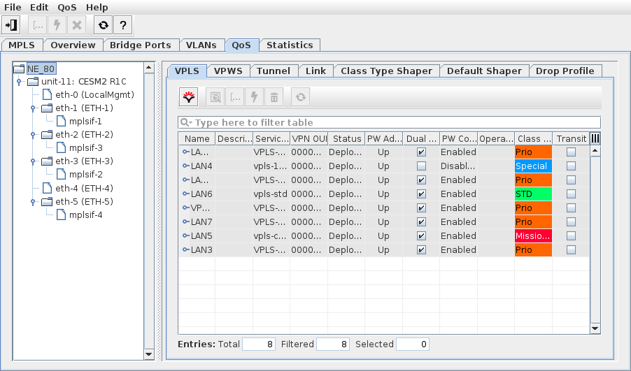
In the top icon bar, all defined class type based filter options are available to filter the information displayed in the tables below. As a further filter option, a drop down box to select “All”, “Transit” or “Terminated” elements (services, PWs, tunnels) for the NE.
Where applicable, the information shown is filtered by the item selected in the left-hand tree. The context menu on the element in the tree provides the following commands while in edit mode (edit mode is only available while in Expert Mode; see Options - Expert Mode):
Aligns the NE - QoS - Class Type Shaper settings with the properties of the selected HQoS profile.
• Clear
Clear all input fields of the dialog that have been modified in the edit mode.
The information on the right hand side is presented under the following tabs:
• NE Details: QoS: VPLS
Provides the same features as the VPLS tab in the ENP main window, but filtered for the current NE,
• NE Details: QoS: VPWS
Provides the same features as the VPWS tab in the ENP main window, but filtered for the current NE,
• NE Details: QoS: Pseudo Wire
Provides the same features as the Pseudo Wire tab in the ENP main window, but filtered for the current NE,
• NE Details: QoS: Tunnel
Provides the same features as the Tunnel tab in the ENP main window, including the “Transit” parameter, but filtered for the current NE,
• NE Details: QoS: Link
Provides the same features as the Link tab in the ENP main window, but filtered for the current NE,
• NE Details: QoS: Class Type Shaper
The used Shape Buffer ratio (percentage) and the free bytes are indicated in the upper right corner of the dialog window. Only available if the NE supports BW enforcement.
Operations:
After activating Options - Expert Mode, the following operations are available:
− Edit (via Edit icon): edit the shaper settings for any of the entries in the table. Select any entry and modify its settings in the parameter list at the bottom as far as these are editable.
While in Edit mode:
− Deploy: deploy the shaper settings to the NE.
− Cancel: cancel the shaper modifications and return to view-only mode.
− Add: add a new Class Type shaper.
− Remove: delete selected Class Type shaper(s) from the list.
− Align: align the Class Type shaper settings to their default (one of the HQoS profiles is required). Return to the view mode.
− Clear: clear the Class Type shaper settings.
Parameters: Shaper (identifier); Use Defaults; Port; Interface; Class Type; Status; Profile; BW Enforcement; CIR; CBS; EIR; EBS; Priority; Scheduling Profile; Drop Profiles DP TC0, …, DP TC7).
• NE Details: QoS: Default Shaper
Only available if the NE supports BW enforcement.
Operations:
− Edit: edit the default shaper settings for any of the entries in the table. Select any entry and modify its settings in the parameter list at the bottom as far as these are editable.
− Deploy: deploy the default shaper settings to the NE.
− Cancel: cancel the default shaper modifications and return to view-only mode.
− Align: align the default shaper settings to default.
− Clear: clear the default shaper settings.
Parameters: Use Default; Port; Profile; Status; BW Enforcement; CIR; CBS; EIR; EBS; Priority; Drop Profiles DP TC0, …, DP TC7).
• NE Details: QoS: Drop Profile
Only available if the NE supports BW enforcement.
Operations: Add, Delete. You can only add a new drop profile if the maximum (50) is not yet reached.
Parameters: Index, Threshold, Status (Deployed Valid, Deployed Invalid, Deployed Delete). Status is available in view mode, but not in edit mode.
NE Details: Statistics
Lists all MPLS-TP relevant units of the current NE and their Ethernet ports. To see all available ports expand the unit by double-clicking on the unit name in the NE tree window. For any such port Ethernet packet statistics can be displayed provided an appropriate PM collection job has been defined for that port:
• ports with PM data are marked with a green square;
• ports without PM data are marked with a blank square.
Dialog image
NE - Statistics
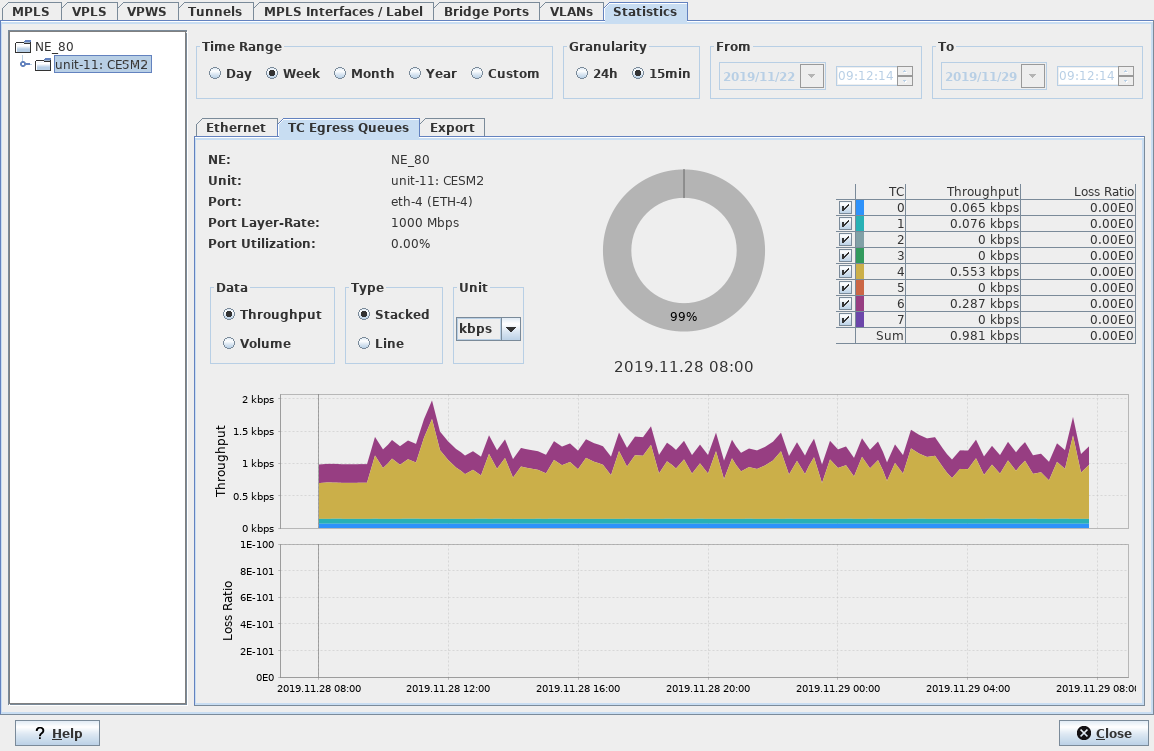
The image above shows sample statistics graphs for a core unit front port. For more information on the statistics displayed also refer to Link Details - Statistics.
Related dialogs / windows
Link Details - Statistics.
Add NEs
Name | The Name of the NE given when creating or discovering the NE. This information is read-only. |
Global ID | Allows you to set/modify Global ID of NEs which are not yet member(s) of the ENP-Nodes Domain. Double-click the field to edit. |
Node ID | Allows you to set/modify Node ID of NEs which are not yet member(s) of the ENP-Nodes Domain. Double-click the field to edit. |
Description | Allows you to set/modify Description(s) of NEs which are not yet member(s) of the ENP-Nodes Domain. |
State | The modification state of the Node ID, Global ID, and/or Description. - Empty: When no modification has been made to the Node ID, Global ID or Description, this field is empty. - Modified: When Node ID, Global ID and/or Description have been modified the field is set to “Modified”. In this case the “Deploy Modifications” button is activated. - Deploying: The modifications are currently being deployed. - Deployed Valid: The modifications have been deployed and are valid. - Deployed Invalid: The modifications have been deployed, but the entered data is invalid. Make sure that especially the Node ID / Global ID set is valid, re-enter corrected values and deploy again. |
NE Operational State | Shows whether the NE is “Manageable” or “Not manageable”. This information is read-only. This is the same information as shown in the NEM Configurator as “Operational State”. |
Deploy Modifications | Deploys the modifications (Global ID/Node ID or Description) to the nodes. |
Add to ENP Domain | Adds the selected NEs to the ENP-Nodes Domain. |
? Help | Calls the help viewer and opens this page. |
Close | Closes the dialog. |
Related dialogs / windows