
Create VPLS
Purpose
Please note:
When Expert Mode is enabled in the Options menu of the ENP main window, the Create VPLS wizard allows you to create on a single NE VPLS two VPWS with split horizon, or other VPLS, without consistency check.
→ Use the Expert Mode only if you are a highly experienced user.
The “Create Service” dialog allows you to create a VPLS (full mesh), an H-VPLS (mesh/spoke), or to add NEs as PE dual home NEs:
• For VPLS (mesh) execute steps 1 to 7, without doing any selection in step 4.
• For H-VPLS (mesh/spoke) execute steps 1 to 7, while selecting and defining ports of spoke NEs in step 4 as far as required.
• For VPLS with Dual Home option, in step 2 (Define VPLS NEs), select the “Role” of the NE that needs to be attached as PE Dual Home NE.
The dialog supports you with service creation by proposing many default settings. A number of manual settings are required however. These are mentioned in the step explanations under “Controls (buttons, menu items, etc.)” below.
When called from the “Modify VPLS…” menu selection the “Create Service” dialog allows you to add VPLS NEs (nodes) to an existing VPLS service or remove VPLS NEs (nodes) from an existing VPLS service. In this case the parameters in Step 2: Define VPLS NEs and Step 3 - “VPWS Ports” tab can be modified. The other parameters are read-only.
Please note:
A service created with this dialog is saved to the database but not automatically deployed to the nodes. In order to deploy the services to the nodes you need to select the service in the VPLS tab of the ENP main window and execute “Deploy VPLS” from the “Edit” menu or from the context menu.
You can execute this command with a maximum of 5 concurrently selected services at a time.
Dialog image
Define Service
Mandatory entries
Define Service:
− without TE Service Profile license option: none
− with TE Service Profile license option: Service Profile
− where required: set “Dual Home Capable”
Define Quality of Service / Rate Limiting: none
Define VPLS NEs
− Select Member NEs
− Enter SVI VLAN
− For PE Dual Home relevant NEs select primary node and secondary node, and protection mode.
− For Spoke NEs select primary node to connect to.
Define VPLS Topology
− where required: add VPWS ports to the service;
− where required: edit Pseudo Wires;
− where required: define / edit port rate limiters.
Define Tunnels
− where required: modify the bandwidth (PW, Tunnel);
− where required: select and/or route the tunnel(s).
Create tunnel(s) – only when tunnels are to be created manually
Summary
− Save
Optional entries
Define Service
− Name (default name is given – this can be edited)
− Type (default is “VPLS”)
− Description
Note:
The use of Service Profiles is strongly recommended. It assures a consistent setting of the relevant parameters throughout the MPLS-TP network.
With a valid TE Service Profile license option the selection of a Service Profile is mandatory for the service definition.
− Add To Service Supervision
− Network
− Customer
− SLA
Define Quality of Service / Rate Limiting:
− CoS Type
− Default Priority
− Scheduling Profile
− CoS Overwrite
− Overwrite Priority
− Enable Rate Limiting
− CIR
− CBS
− EIR
− EBS
Define VPLS NEs
− For PE Dual Home relevant NEs select primary node and secondary node, and protection mode.
− For Spoke NEs select primary node to connect to.
Define VPLS Topology
− Add selected ports of non-fully meshed NEs to the service;
− Select VPWS type, AC VLAN and/or PW VLAN, depending on VPWS type, and “Attached to NE”.
− where required: edit Pseudo Wires;
− where required: define / edit port rate limiters; set CIR, CBS, EIR, EBS.
Define Tunnels
− where required: modify the bandwidth (PW, Tunnel);
− where required: select and/or route the tunnel(s).
Create tunnel(s) manually – only when tunnels are to be created manually
Summary
− Verify service summary.
Informational content
All dialogs
Steps | Displays the steps to create a Service. |
Summary | Displays the currently configured/selected mandatory parameters. |
Controls (buttons, menu items, etc.)
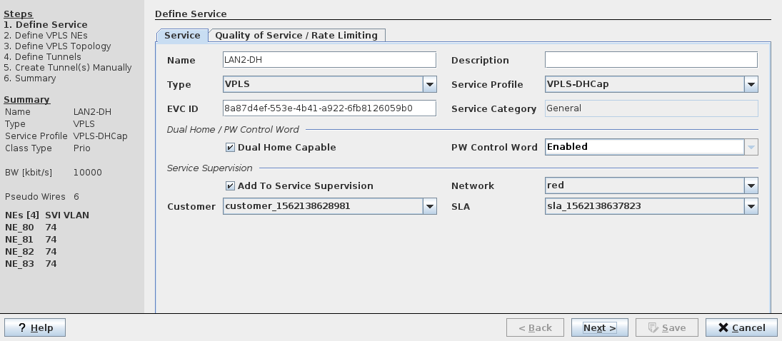
Step 1: Define Service, tab “Service”
Name | Specify a Name for the VPLS. A default name is proposed that can be taken over. The name can be edited manually. Note: The Name must be unique and shall not contain characters like [ ] / | * ? { } = |
Description | Enter a description for the VPLS. |
Type | Specify Service Type: - VPLS (default setting shall be taken over; however, if required you can change the service type here). |
Select a Service Profile from the list of existing Service Profiles. This entry is mandatory with a TE Service Profile license option, otherwise it is optional. Note: If you want to create a VPLS based on a Service Profile but need to configure some of the service parameters make sure to use a profile with the relevant parameter options set to “Variable” instead of “Fixed”. For details refer to Create Service Profile. | |
EVC ID | An automatically generated and assigned Ethernet Virtual Connection ID. |
Service Category | Shows the service category defined by the service profile. |
Dual Home / PW Control Word settings: | |
Dual Home Capable | Can be enabled or disabled as specified by the service profile. For General services the “Dual Home Capable” option is enabled by default; for “Transparent Clock” services the “Dual Home Capable” option is always disabled; for “Transparent Clock with CW” services the “Dual Home Capable” option is enabled. |
PW Control Word | Sets the PseudoWire Control Word to enabled or disabled. For dual home capable services the PW Control Word must be enabled. For non-dual home capable services the PW Control Word can be disabled if required. A service with PTP mode “Transparent Clock” can only be used for PTP if the PW Control Word is disabled. For PTP mode “Transparent Clock with CW” Control Word must be enabled. |
Service Supervision settings: | |
Add To Service Supervision | Click the “Add To Service Supervision” checkbox to activate the Service Supervision parameters: - Network, - Customer, - SLA. Note: These options can only be selected if Service Supervision and Reporting has been configured. If selected, this adds the service to the monitored services under the Service Supervision Service Supervision. A monitored Service must be deployed. |
Network | Select the Network attributes for the Service: - red, - green, - blue, - yellow. Note: The network is an attribute that allows coloring and filtering paths and components according to their physical implementation. Refer to Service Editor section for details. |
Customer | Select a Customer profile from the Customer Manager list. |
SLA | Select a Service Level Agreement profiles from the SLA Manager list. |
Step 1: Define Service, tab “Quality of Service / Rate Limiting”
Ingress Port QoS settings: | |
CoS Type | Select the Class of Service Type from one of the following: - Interface: Apply a port based traffic classification. - PCP-1: use the PCP to Traffic Class mapping table as configured via the FOXCST GUI: NE – QoS – To TC Mapping. - DSCP-1: use the DSCP to Traffic Class mapping table as configured via the FOXCST GUI: NE – QoS – DSCP to PHB, PHB to PSC, PSC to TC Mapping. Note: This parameter and all further parameters of this step cannot be selected when a service profile has been applied in step 1 with this parameter set to “Fixed”. |
Default Priority | Select the default priority to be applied from the range 0…7. |
Ingress CoS for VLAN Based services settings: | |
CoS Overwrite | Defines the CoS overwrite mode as set in the service profile. |
Overwrite Priority | Defines the overwrite priority in the range 0…7 as set in the service profile. Applies only when “CoS Overwrite” mode is set to “Overwrite”. |
Ingress Rate Limiting settings: | |
Enable Rate Limiting | Enable or disable Rate Limiting. Note: This parameter cannot be selected when a service profile with fixed parameters has been applied in step 1. |
Committed Information Rate [kbit/s] | If Rate Limiting is enabled, enter the CIR in kbit/s. |
Committed Burst Size [Bytes] | If Rate Limiting is enabled, enter the CBS in bytes. |
Excess Information Rate [kbit/s] | If Rate Limiting is enabled, enter the EIR in kbit/s. |
Excess Burst Size [Bytes] | If Rate Limiting is enabled, enter the EBS in bytes. |
Egress Scheduling Profile settings: | |
Scheduling Profile | Select one of the available scheduling profiles. The scheduling profile 1 is fixed to strict priority scheduling. The scheduling profiles 2…5 can be edited via the FOXCST GUI: NE – QoS – TC Scheduling Profiles – Profile 2…5. |
Step 1: General Navigation
? Help | Calls the help viewer and opens this page. |
Next > | Calls the next dialog. Only available when all the mandatory parameters of the currently opened dialog are entered or selected. |
Save | Closes the dialog and saves the Service to the database. Note: The “Save” button is activated only when all the mandatory parameters of the currently opened dialog are entered or selected. A confirmation is issued when the service has been saved to the database. To deploy a service select the service in the VPLS tab of the ENP main window, then select “Deploy VPLS” from the menu. |
Cancel | Closes the dialog without creating the Service. |
Step 2: Define VPLS NEs
This steps includes an option to modify the Port Type of involved ports on the selected NEs. Modified port types will be applied to the network after user approval and will be confirmed by FOXMAN‑UN via a message “Alignment SniPort succeeded”.
Left-hand table with VPLS NEs to be selected for the service: | |
VPLS NE | Choose the VPLS member nodes from the list of available ENP nodes. The selected NEs appear in the list of VPLS NEs in the Summary on the left hand side. Note: When a VPLS NE is selected in the table, and a SVI VLAN has been entered all suitable ports for the VPLS are displayed in a sub-table on the right hand side of the dialog window. For the columns of the sub-table see “Right-hand table with ports listed for selected NE:”. A VPLS cannot be saved while it includes ports with active conflicts. |
NE | The specified Name of the NE. |
SVI VLAN | Enter a VLAN ID in the range [1…4089] for any NE. If the SVI VLAN does not yet exist it will be created. The entered SVI VLAN ID will be applied to all NEs for the new service. Note: If a wrong port mode or any other conflicting setting is encountered an error message will be issued. |
VLAN Name | Name for the SVI VLAN. If the SVI VLAN does not yet exist a name for it will be created automatically. |
Role | The role of the NE in the network: - Hub (default), - Spoke, - PE Dual Home. Note: - The Hub NEs will be connected to each other by Pseudo Wires full mesh. - Spoke NE role is only applicable if there is a mesh network available for the related NE. When selected, the name of the attached NE appears in the column “Primary Node”. - PE Dual Home role requires primary node, secondary node, and protection mode to be set. |
Primary Node | For VPLS NE with “PE Dual Home” role, select the primary NE to which the current VPLS shall be connected. For “Spoke” role, select the primary NE to which the VPLS NE shall be connected. To select a primary node, click into the field and select from the drop-down list. |
Secondary Node | For VPLS NE with “PE Dual Home” role, select the secondary NE to which the current VPLS shall be connected. To select a primary node, click into the field and select from the drop-down list. |
Protection Mode | Select the PE Dual Home protection mode (Revertive, Non-Revertive) to be applied. |
WTR Time | Set the Wait To Restore Time to be applied for switching back after a protection switch-over in the range 5 … 720 seconds. Default is 300 seconds. |
Status | Indicates missing settings or steps. If an SVI VLAN is not set, the field shows “VLAN Id not set”. If an SVI VLAN has been entered, the field shows “Unsaved” to indicate that the VLANs haven’t been saved yet. The VLANs are saved in a later step. If an NE has all required settings available, and which are saved already, the status is “Saved OK”. If an NE has been added but not saved yet, the status is “Unsaved”. |
Right-hand table with ports listed for selected NE: | |
Edit |  Switch to edit mode. The edit mode allows you to modify ports before adding them to the service. The modification can be applied directly to the network. Also used to switch back to View mode. Switch to edit mode. The edit mode allows you to modify ports before adding them to the service. The modification can be applied directly to the network. Also used to switch back to View mode. |
Apply | |
Reload | |
While in “View” mode: | |
NE | Shows the NE name. |
Reference | Shows the port reference. |
VLAN Mode | Shows the VLAN mode applicable to the port. |
Status | Shows the save status of the VLAN port. |
Conflict | Indicates whether there is a conflict that would exclude the port from being added to the service. |
Reason | Indicates the most probable conflict reason. |
While in “Edit” mode: | |
Port | Checkbox to mark a port to be added. A port marked here is added to the VPLS if it can be re-configured accordingly, i.e., when marked, the Port Type and VLAN Mode of a port are modified (to “CVP, Trunk” or “CVP, General”) so that it can be added to the VPLS. If you select a different NE, you will be prompted with a confirmation request asking whether you want to apply the port modifications (Yes, No). - Yes: port modifications will be applied, which will take some time and will be confirmed by a message “Alignment SniPort succeeded”, and the ports are added to the VPLS. Note: Applied port modifications will remain in the network even if you cancel the service creation or modification. - No: port modifications will be canceled, and the ports won’t be added to the VPLS. |
Label | Address of the port including unit, slot, and port ID. |
Slot | The slot number of the unit in the NE subrack. |
Port Type | The port type configured on the port (None, CVP, PWAC). |
VLAN Mode | The VLAN mode configured on the port (Unknown, General, Trunk, Access). |
Reason | Indicates the most probable conflict reason. |
Show all ports | Checkbox to be marked if all ports shall be displayed, including the ones not eligible for being added to the VPLS. |
Step 2: General Navigation
? Help | Calls the help viewer and opens this page. |
< Back | Calls the previous dialog. |
Next > | Calls the next dialog. Only available when all the mandatory parameters of the currently opened dialog are entered or selected. |
Save | Closes the dialog and saves the Service to the database. Note: The “Save” button is activated only when all the mandatory parameters of the currently opened dialog are entered or selected. A confirmation is issued when the service has been saved to the database. To deploy a service select the service in the VPLS tab of the ENP main window, then select “Deploy VPLS” from the menu. |
Cancel | Closes the dialog without creating the Service. |
Step 3: Define VPLS Topology
Step 3 - “VPLS Topology” tab
The “VPLS Topology” tab shows the topology settings made in step 2.
Node | Name of the node that is part of the topology. |
Role | The role of the NE in the network: - Hub (default), - Spoke, - PE Dual Home. Note: - The Hub NEs will be connected to each other by Pseudo Wires full mesh. - Spoke NE role is only applicable if there is a mesh network available for the NE. The name of the attached NE appears in the column “Primary Node”. - When the NE has PE Dual Home role, primary node and secondary node NEs are shown in the two respective columns. |
Primary Node | For VPLS NE with “PE Dual Home” role, shows the primary NE to which the current VPLS is connected. |
Secondary Node | For VPLS NE with “PE Dual Home” role, shows the secondary NE to which the current VPLS is connected. |
Connected | Shows whether an NE is connected in the scope of this service. |
Node | Name of the NE with preceding short for the mode: H: Hub S: Spoke PE: PE Dual Home |
Node PW Binding | PW Binding of the node and its connected node in the scope of the current service. Valid options are “Mesh” or “Spoke”. |
Connected To | Name of the connected NE with preceding short for the mode: H: Hub S: Spoke PE: PE Dual Home |
Connected To PW Binding | PW Binding of the connected node and its connected node in the scope of the current service. Valid options are “Mesh” or “Spoke”. |
Dual-Home Group | Name of the Dual-Home group. You can select among the PE Dual Home node name or “No Dual-Home Group”. |
Dual-Home Role | Primary or Secondary node. |
PW Name | Name of the PW used for this service between node and “Connected To” node. |
PW Description | Description of the PW. |
PW BW [kbit/s] | Configured bandwidth of the PW. |
Step 3 - “VPWS Ports” tab
Add VPWS Ports to Service (optional). This step is required only if you want to define VPWS NE ports to be attached to the service. Otherwise, go to the “Pseudo Wire” tab.
NE, Name | Select an NE from the list of NEs. The available ports appear in the Ports list on the right. Note: This is applicable only to spoke bindings. No setting shall be done here for full mesh bindings. |
Right-hand table with ports of the selected NE: | |
Port | Select one or several ports from the list by activating the mark in the checkbox. Ports of Port Type “CVP” or “PWAC” are listed here. Repeat this for all required spoke NEs. |
Label | Shows the port label composed of <NE Name> <Unit Name> <slot> <port-x> |
Port Type | Shows the Port Type. Only CVP or PWAC ports are available. |
VPWS Type | Choose the Attachment Circuit (AC) type. The AC type depends on the selected Port Type (CVP, PWAC). The list of Types includes: - AC Port Based, No Change, - AC Port Based, Add PW Tag, - AC VLAN Based, No Change, - AC VLAN Based, Change Tag, - AC VLAN Based, Add PW Tag, - AC Untagged, No Change, - AC Untagged, Add PW Tag. Note: Depending on the Port Type only a part of the above options appear in the “Type” selection list. |
AC VLAN | Enter an existing AC VLAN ID (Attachment Circuit VLAN) for each port if “Type” is set to: - AC VLAN Based, No Change, - AC VLAN Based, Change Tag, or - AC VLAN Based, Add PW Tag. No AC VLAN can be entered for “Type” set to: - “AC Port Based, No Change”, - “AC Port Based, Add PW Tag”, - “AC Untagged, Add PW Tag”, or - “AC Untagged, No Change”. |
PW VLAN | Enter a PW VLAN ID in the range 1…4089 for each port if one of the following is selected in “Type”: - “AC Port Based, Add PW Tag”, - “AC VLAN Based, Change Tag”, - “AC VLAN Based, Add PW Tag”, or - “AC Untagged, Add PW Tag”. |
Attached to NE | From the drop down list select the (spoke) NE to which the port is attached. |
Status | Shows the status of the Ports setup. Usually this will show “Unsaved” until the configuration has been saved. In case of any conflict the Status column shows the most probable reason for the conflict. Example: “VLAN Id already in use” is shown if the AC VLAN ID is already used for other VLAN settings. |
Reason | Shows the reason for which a port cannot be added to the service. |
Show all ports | When enabled, the ports table also shows ports that cannot be added due to a configuration mismatch between port settings and service requirements. |
Step 3: “Pseudo Wire” tab
In this tab the determined Pseudo Wires are listed. Some of their properties need to be configured now. If a Service Profile has been selected in step 1 the bandwidth (BW) is already determined.
Please note:
Parameters that have been set to “Variable” in the Service Profile can still be edited here. Parameters that have been set to “Fixed” in the Service Profile can no longer be edited here.
The entries can either be done within the table, or in the “Pseudo Wire(s)” details field below the table once an entry has been selected.
Name | Specify a Name for the Pseudo Wire. You can accept the automatically generated name. Note: The Name must be unique and shall not contain characters like [ ] / | * ? { } = |
Description | Enter a description for the Pseudo Wire. This entry is optional. |
Initiator | Shows the Initiator NE. |
Terminator | Shows the Terminator NE. |
BW [kbit/s] | Enter the allocated bandwidth for the Pseudo Wire in kbit/s. Example: For a bandwidth of 10 Mbit/s enter 10000. |
Tunnel, Select Tunnel:  | When clicking into the “Tunnel” field or on the Tunnel selection icon, you can select/edit the tunnel to be used for the service. Select one of the following: - Create Automatically, - Create Manually, - or select one of the existing tunnels (if applicable). Once the “Next >” button is clicked, the Wizard will proceed to Step 6 Create Tunnel. Note: - The list includes only applicable Tunnels, i.e. Tunnels with sufficient bandwidth and the same endpoints as the currently being created Service. - If any of the existing tunnels or “create automatically” option is selected, the Wizard will skip the Step 6 “Create Tunnel”. |
Min Label | The minimum Pseudo Wire label (recommended default: 500000; allowed range: 16 to 1048575). |
Max Label | The maximum Pseudo Wire label (default: 1048575; allowed range: 500000 to 1048575). |
Status | Shows the status of the Ports setup. Usually this will show “Unsaved” until the configuration has been saved. In case of any conflict the Status column shows the most probable reason for the conflict. |
Step 3: “Port Rate Limiter” tab
In this tab the rate limiting parameters CIR, CBS, EIR, EBS can be modified if modification is allowed in the service profile used. You need to select a port from the Ports List for modification of its Parameters.
Please note:
Parameters that have been set to “Variable” in the Service Profile can still be edited here. Parameters that have been set to “Fixed” in the Service Profile can no longer be edited here.
Ports List
NE | Shows the NE name. |
Reference | Shows the port reference with unit name, slot, and port ID. |
VLAN Mode | Shows the configured VLAN mode of the port. |
Status | Shows the save status of the port’s assignment to the service. |
Parameters
NE | Shows the NE name as selected in the Ports List. |
Port | Shows the port reference with unit name, slot, and port ID as selected in the Ports List. |
CoS Type | Shows the CoS Type set in the service profile. |
Default Priority | Shows the Default Priority set in the service profile. |
Scheduling Profile | Shows the Scheduling Profile set in the service profile. |
CoS Overwrite | Shows the CoS Overwrite set in the service profile. |
Overwrite Priority | Shows the Overwrite Priority set in the service profile. |
Enable Rate Limiting | Select whether to enable or disable rate limiting. |
Committed Information Rate [kbit/s] (CIR) | If rate limiting is enabled, enter the required CIR for the selected port. |
Committed Burst Size [bytes] (CBS) | If rate limiting is enabled, enter the required CBS for the selected port. |
Excess Information Rate [kbit/s] (EIR) | If rate limiting is enabled, enter the required EIR for the selected port. |
Excess Burst Size [Bytes] (EBS) | If rate limiting is enabled, enter the required EBS for the selected port. |
Step 3: General Navigation
? Help | Calls the help viewer and opens this page. |
< Back | Calls the previous dialog. |
Next > | Calls the next dialog. Only available when all the mandatory parameters of the currently opened dialog are entered or selected. If any manual tunnel creation has been selected, the tunnel creation dialog is now displayed. If all tunnels have been set to “Create Automatically” the tunnel creation runs without showing a specific dialog. Only available when all the mandatory parameters of the currently opened dialog are entered or selected. |
Save | Closes the dialog and saves the Service to the database. Note: The “Save” button is activated only when all the mandatory parameters of the currently opened dialog are entered or selected. A confirmation is issued when the service has been saved to the database. To deploy a service select the service in the VPLS tab of the ENP main window, then select “Deploy VPLS” from the menu. |
Cancel | Closes the dialog without creating the Service. |
Step 4: Define Tunnel(s)
The table in this step lists Pseudo Wires and their tunnels. The Initiator and Terminator are taken from the Pseudo Wire and cannot be changed. Depending on the number of ports and related settings, this step may take some time. It will be executed for each of the required tunnels before proceeding to Step 6: Summary.
Pseudo Wire | Name of the Pseudo Wire used. |
Initiator | Name of the Initiator NE with preceding short for the mode: H: Hub S: Spoke PE: PE Dual Home |
Terminator | Name of the Terminator NE with preceding short for the mode: H: Hub S: Spoke PE: PE Dual Home |
Pseudo Wire BW [kbit/s] | Current bandwidth of the PW. Edit this if required. |
Tunnel BW [kbit/s] | Current bandwidth of the Tunnel. Edit this if required. |
Mode | Shows whether the entry has been modified or is saved already. |
Tunnel | Name of the Tunnel used. |
Tunnel Status | Deployment status of the Tunnel. |
Tunnel Action | Shows required action(s) for the Tunnel. The proposed actions can be taken manually by editing the appropriate characteristics, or by clicking on the tunnel selection icon below the table. The following options are available: - Create Manually - Create Automatically - Modified. The “Modified” option allows you to select - the current tunnel but with corrected settings according to the “Tunnel Action” field, or - any other appropriate tunnel. |
Error | Shows possible errors that might prevent selecting the tunnel. |
Step 4: General Navigation
? Help | Calls the help viewer and opens this page. |
< Back | Calls the previous dialog. |
Automatic Routing | Starts automatic routing, i.e. creates the required tunnels and/or modifies existing tunnels before the “Next >” button is activated. |
Next > | Calls the next dialog. Only available when all the mandatory parameters of the currently opened dialog are entered or selected. |
Save | Creates the required tunnels, saves the service to the database and closes the wizard. Note: The “Save” button is activated only when all the mandatory parameters of the currently opened dialog are entered or selected. A confirmation is issued when the service has been saved to the database. To deploy a service select the service in the VPLS tab of the ENP main window, then select “Deploy VPLS” from the menu. |
Cancel | Closes the dialog without creating the Service. |
For a description of parameters in the “Details Tunnel” dialog, please refer to the Create Tunnel section.
Step 5: Create Tunnel(s) Manually
This step is only used when tunnels are set to be created manually in the previous step.
Step 6: Summary
Shows a summary of the service settings.
? Help | Calls the help viewer and opens this page. |
< Back | Calls the previous dialog. |
Save | Closes the dialog and saves the Service to the database. Note: A confirmation is issued when the service has been saved to the database. To deploy a service select the service in the VPLS tab of the ENP main window, then select “Deploy VPLS” from the menu. |
Cancel | Closes the dialog without creating the Service. |
Final step: Deploy Service:
Once the service is created and saved it needs to be deployed to the nodes. This is done by selecting the service from the list of VPLS in the ENP main window and executing the menu option “Deploy VPLS”.
Table Sorting and Filtering/Export and Printing
Please refer to Table Sorter section for details.
Related dialogs / windows
Service Profile (depends on license option),