
Create VPWS
Purpose
The “Create Service” dialog allows you to create a Virtual Private Wire Service (VPWS).
The dialog supports you with service creation by proposing many default settings. A number of manual settings are required however. These are mentioned in the step explanations under “Controls (buttons, menu items, etc.)” below.
Please note:
A service created with this dialog is saved to the database but not deployed to the nodes. In order to deploy the services to the nodes you need to select the service in the VPWS tab of the ENP main window and execute “Deploy VPWS” from the “Edit” menu or from the context menu.
You can execute this command with a maximum of 5 concurrently selected services at a time.
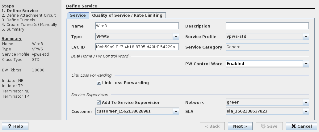
Dialog image
Define Service
Mandatory entries
Define Service:
− without TE Service Profile license option: none
− with TE Service Profile license option: Service Profile
Define Quality of Service / Rate Limiting: none
Define Attachment Circuit:
− Initiator Type / Terminator Type
− Initiator AC / Terminator AC
Define Pseudo Wire(s):
− Min/Max Label
− Tunnel
Create Tunnel(s)
Finish
− Save
Deploy
Optional entries
Define Service:
− Name (default name is given – this can be edited)
− Type (default is “VPLS”)
− Description
Note:
The use of Service Profiles is strongly recommended. It assures a consistent setting of the relevant parameters throughout the MPLS-TP network.
With a valid TE Service Profile license option the selection of a Service Profile is mandatory for the service definition.
Define Quality of Service / Rate Limiting:
− CoS Type
− Default Priority
− Scheduling Profile
− CoS Overwrite
− Overwrite Priority
− Enable Rate Limiting
− CIR
− CBS
Define Attachment Circuit (optional parameters depend on Initiator/Terminator Type):
− Initiator AC VLAN
− Initiator PW VLAN
− Terminator AC VLAN
− Terminator PW VLAN
− Port Type for AC port(s)
Service Supervision
BW [kbit/s]
Informational content
All dialogs
Steps | Displays the steps to create a Service. |
Summary | Displays the currently configured/selected mandatory parameters |
Controls (buttons, menu items, etc.)
Step 1 (a): Define Service, tab “Service”
Name | Specify a Name for the VPWS. A default name is proposed that can be taken over. However the name can be edited manually. Note: The Name must be unique and shall not contain characters like [ ] / | * ? { } = |
Description | Enter a description for the Service. |
Type | Specify Service Type: - VPWS (default setting shall be taken over; however, if required you can change the service type here) |
Select a Service Profile from the list of existing Service Profiles. This entry is mandatory with a TE Service Profile license option. Note: If you want to create a VPWS based on a Service Profile but need to configure some of the service parameters individually make sure to use a profile with the relevant parameter options set to “Variable” instead of “Fixed”. For details refer to Create Service Profile. | |
EVC ID | An automatically generated and assigned Ethernet Virtual Connection ID. |
Service Category | Shows the service category defined by the service profile. |
Dual Home / PW Control Word settings: | |
PW Control Word | Sets the PseudoWire Control Word to enabled or disabled. For dual home capable services the PW Control Word must be enabled. For non-dual home capable services the PW Control Word can be disabled if required. A service with PTP mode “Transparent Clock” can only be used for PTP if the PW Control Word is disabled. For PTP mode “Transparent Clock with CW” (preferred / default service category for transparent lock) the PW Control Word must be enabled. When using an EPEX1 unit in any of the involved nodes, the use of “Transparent Clock with CW” is mandatory for PTP mode “Transparent Clock”. |
Link Loss Forwarding settings: | |
Link Loss Forwarding | Click the “Link Loss Forwarding” checkbox to activate LLF for the service. When enabled, LLF will signal a local link down over the PW of a port-based VPWS and replicate the link down on the remote port. This feature is needed where the VPWS is used as a super-transparent wire service, e.g. when transporting an RSTP link over MPLS-TP. Default is “Enabled”. |
Service Supervision settings: | |
Add To Service Supervision | Click the “Add To Service Supervision” checkbox to activate the Service Supervision parameters: - Network, - Customer, - SLA. Note: These options can only be selected if Service Supervision and Reporting has been configured. If selected, this adds the service to the monitored services under the Service Supervision Service Supervision. A monitored Service must be deployed. |
Network | Select the Network attributes for the Service: - red, - green, - blue, - yellow. Note: The network is an attribute that allows coloring and filtering paths and components according to their physical implementation. Refer to Service Editor section for details. |
Customer | Select a Customer profile from the Customer Manager list. |
SLA | Select a Service Level Agreement profiles from the SLA Manager list. |
Step 1 (b): Define Service, tab “Quality of Service / Rate Limiting”
Ingress Port QoS settings: | |
CoS Type | Select the Class of Service Type from one of the following: - Interface: Apply a port based traffic classification. - PCP-1: use the PCP to Traffic Class mapping table as configured via the FOXCST GUI: NE – QoS – To TC Mapping. - DSCP-1: use the DSCP to Traffic Class mapping table as configured via the FOXCST GUI: NE – QoS – DSCP to PHB, PHB to PSC, PSC to TC Mapping. Note: This parameter cannot be selected when a Service Profile has been applied in step 1 with this parameter set to “Fixed”. |
Default Priority | Select the default priority to be applied from the range 0…7. Note: For VLAN based services the default priority is ignored. |
Ingress CoS for VLAN Based services settings: | |
CoS Overwrite | Defines the CoS overwrite mode as set in the service profile. |
Overwrite Priority | Defines the overwrite priority in the range 0…7 as set in the service profile. Applies only when “CoS Overwrite” mode is set to “Overwrite”. |
Ingress Rate Limiting settings: | |
Enable Rate Limiting | Enable or disable Rate Limiting. Note: This parameter cannot be selected when a Service Profile has been applied in step 1. |
Committed Information Rate [kbit/s] | If Rate Limiting is enabled, enter the CIR in kbit/s. |
Committed Burst Size [Bytes] | If Rate Limiting is enabled, enter the CBS in bytes. |
Excess Information Rate [kbit/s] | If Rate Limiting is enabled, enter the EIR in kbit/s. |
Excess Burst Size [Bytes] | If Rate Limiting is enabled, enter the EBS in bytes. |
Egress Scheduling Profile settings: | |
Scheduling Profile | Select on of the five scheduling profiles. The scheduling profile 1 is fixed to strict priority scheduling. The scheduling profiles 2…5 can be edited via the FOXCST GUI: NE – QoS – TC Scheduling Profiles – Profile 2…5. |
Step 1: General Navigation
? Help | Calls the help viewer and opens this page. |
< Back | Calls the previous dialog. |
Next > | Calls the next dialog. Only available when all the mandatory parameters of the currently opened dialog are entered or selected. |
Save | Closes the dialog and saves the Service to the database. Note: The “Save” button is activated only when all the mandatory parameters of the currently opened dialog are entered or selected. A confirmation is issued when the service has been saved to the database. To deploy a service select the service in the VPLS tab of the ENP main window, then select “Deploy VPLS” from the menu. |
Cancel | Closes the dialog without creating the Service. |
Step 2 (a): Define Attachment Circuit, tab “Attachment Circuit”
For both Initiator and Terminator select the required set of parameters as follows:
AC |  | Calls the Attachment Circuit (AC) dialog to select the AC NE. |
Type | This type defines the AC’s frame handling and VLAN tag handling. Select the Initiator Type and the Terminator Type from the list: - AC Port Based, No Change, - AC Port Based, Add PW Tag, - AC VLAN Based, No Change, - AC VLAN Based, Change Tag, - AC VLAN Based, Add PW Tag, - AC Untagged, No Change, - AC Untagged, Add PW Tag. Note: The type defines first the AC frame handling: - AC Port Based: The AC frame can be untagged, priority tagged or VLAN tagged. - AC VLAN Based: The AC frame must be VLAN tagged. - AC Untagged: The AC frame must be untagged. The type further defines the AC VLAN handling: - No Change: The AC frames are not modified. - Add PW Tag: Add a PW VLAN tag to the AC frames. - Change Tag: The AC VLAN ID is modified to the PW VLAN ID. The list below provides an overview of the possible configuration parameters per type: - AC Port Based, No Change: AC VLAN and PW VLAN are not shown and cannot be modified. - AC Port Based, Add PW Tag: Enter the PW VLAN: <VID PW>. - AC VLAN Based, No Change: Enter the AC VLAN: <VID ETH>. PW VLAN: takes the configured value of AC VLAN. - AC VLAN Based, Change Tag: Enter the AC VLAN: <VID ETH>, Enter the PW VLAN: <VID PW>. - AC VLAN Based, Add PW Tag: Enter the AC VLAN: <VID ETH>, Enter the PW VLAN: <VID PW>. - AC Untagged No Change: AC VLAN and PW VLAN are not shown and cannot be modified. - AC Untagged, Add PW Tag: Enter the PW VLAN: <VID PW>. | |
AC VLAN | Enter the Initiator/Terminator AC VLAN - <VID AC> Accept only tagged frames with the VLAN ID <VID AC> This parameter value is associated with the “AC VLAN Based” service type and can be modified. The valid range is 1…4089. | |
PW VLAN | Enter the Initiator/Terminator PW VLAN: - <VID PW> This parameter value is associated with the “Add PW tag” and “Change Tag” service types and can be modified. The valid range is 1…4089. If the service type is “VLAN Based, No Change”, the PW VLAN ID is copied from the AC VLAN ID and cannot be modified. | |
Port (table) | Select the AC port from the list of available ports. The ports list shows - Label, - Slot, - Port Type: Note: When selecting a port with port type “None” or “CVP”, the port type is automatically set to “PWAC”, and the “Next >” navigation button changes to “Apply Port Types >”. To confirm the port selection and apply the port type modification, click on “Apply Port Types >”. You can manually modify the port type to match the required type “PWAC”; click into the field to modify the port type. The port type cannot arbitrarily be modified. Only types that match the AC Type can be selected. Port types are updated when changing the AC Type. To revert the proposed port type modifications, deselect the port (via <Ctrl>/<Strg>-click), or select a different port, or cancel service creation. Once port types are selected, click on “Apply Port Types >” to apply the modifications to the network. When modifications have been applied, the “Apply Port Types >” button changes back to “Next >”. - VLAN Mode, - Reason (for a port not being selectable when “Show all ports” is enabled). | |
Show all ports | Enable or disable display of all ports, or only of ports that are suitable to be used as AC. When all ports are shown, ports that are not suitable indicate the reason why they cannot be used as AC. |
Step 2 (b): Define Attachment Circuit, tab “Pseudo Wire”
Name | Shows the VPWS name. |
Description | Shows the description for the Pseudo Wire. This entry is optional. |
Initiator | Shows the Initiator NE. |
Terminator | Shows the Terminator NE. |
PW Min Label | Enter the minimum Pseudo Wire label. Default is 500000. It is recommended not to decrease this to avoid conflicts with the tunnel label range. |
PW Max Label | Enter the maximum Pseudo Wire label. Default is 1048575. |
BW [kbit/s] | Enter or edit the allocated bandwidth for the Pseudo Wire in kbit/s. Example: For a bandwidth of 10 Mbit/s enter 10000. |
Step 2 (c): Define Attachment Circuit, tab “Port Rate Limiter”
In this tab the rate limiting parameters CIR, CBS, EIR, EBS can be modified if modification is allowed in the service profile used. You need to select a port from the Ports List for modification of its Parameters.
Please note:
Parameters that have been set to “Variable” in the Service Profile can still be edited here. Parameters that have been set to “Fixed” in the Service Profile can no longer be edited here.
Ports List
NE | Shows the NE name. |
Reference | Shows the port reference with unit name, slot, and port ID. |
VLAN Mode | Shows the configured VLAN mode of the port. |
Status | Shows the save status of the port’s assignment to the service. |
Parameters
NE | Shows the NE name as selected in the Ports List. |
Port | Shows the port reference with unit name, slot, and port ID as selected in the Ports List. |
CoS Type | Shows the CoS Type set in the service profile. |
Default Priority | Shows the Default Priority set in the service profile. |
Scheduling Profile | Shows the Scheduling Profile set in the service profile. |
CoS Overwrite | Shows the CoS Overwrite set in the service profile. |
Overwrite Priority | Shows the Overwrite Priority set in the service profile. |
Enable Rate Limiting | Select whether to enable or disable rate limiting. |
Committed Information Rate [kbits/s] (CIR) | If rate limiting is enabled, enter the required CIR for the selected port. |
Committed Burst Size [bytes] (CBS) | If rate limiting is enabled, enter the required CBS for the selected port. |
Excess Information Rate [kbits/s] (EIR) | If rate limiting is enabled, enter the required EIR for the selected port. |
Excess Burst Size [Bytes] (EBS) | If rate limiting is enabled, enter the required EBS for the selected port. |
Step 2: General Navigation
? Help | Calls the help viewer and opens this page. |
< Back | Calls the previous dialog. |
Next > | Calls the next dialog. Only available when all the mandatory parameters of the currently opened dialog are entered or selected. |
Save | Closes the dialog and saves the Service to the database. Note: The “Save” button is activated only when all the mandatory parameters of the currently opened dialog are entered or selected. A confirmation is issued when the service has been saved to the database. To deploy a service select the service in the VPLS tab of the ENP main window, then select “Deploy VPLS” from the menu. |
Cancel | Closes the dialog without creating the Service. |
Step 3: Define Tunnels
In this step the Pseudo Wire required for the new service is listed. The Initiator and Terminator are taken from the settings in step 2 and cannot be changed.
For descriptions of parameters, please refer to Create Tunnel section.
Pseudo Wire | The name of the Pseudo Wire used for the new service. |
Initiator | Shows the Initiator NE. |
Terminator | Shows the Terminator NE. |
Pseudo Wire BW [kbit/s] | Enter or edit the allocated bandwidth for the Pseudo Wire in kbit/s, or leave the default setting unchanged. Example: For a bandwidth of 10 Mbit/s enter 10000. |
Tunnel BW [kbit/s] | Current bandwidth of the Tunnel. Edit this if required. |
Mode | Shows whether the Tunnel has been modified or is saved already. |
Tunnel (in the table) | When clicking into the selected “Tunnel” field you can select/edit the tunnel to be used for the service. Select one of the following: - Create Automatically, - Create Manually. Once the “Next >” button is clicked, the Wizard will proceed to Step 5 “Create Tunnel”. - One of the existing applicable Tunnels Note: - The list includes only applicable Tunnels, i.e. Tunnels with sufficient bandwidth and the same endpoints as the currently being created Service - If any of the existing tunnels or “create automatically” option is selected, the Wizard will skip the Step 5 “Create Tunnel” and directly proceed with Step 6 “Finish”. |
Tunnel Status | Deployment status of the Tunnel. |
Tunnel Action | Shows required action(s) for the Tunnel. The proposed actions can be taken manually by editing the appropriate characteristics, or by clicking on the tunnel selection icon below the table. The following options are available: - Create Manually - Create Automatically - Modified. The “Modified” option allows you to select - the current tunnel but with corrected settings according to the “Tunnel Action” field, or - any other appropriate tunnel. |
Error | Shows possible errors that might prevent selecting the tunnel. |
Tunnel (below the table) | Shows the currently selected tunnel. You can select automatic or manual tunnel creation or select an existing tunnel by clicking on the selection icon . |
Save Tunnel… | Modifications to the tunnel used for the service can be changed with this command button. |
Step 3: General Navigation
? Help | Calls the help viewer and opens this page. |
< Back | Calls the previous dialog. |
Next > | Calls the next dialog. Only available when all the mandatory parameters of the currently opened dialog are entered or selected. |
Save | Closes the dialog and saves the Service to the database. Note: The “Save” button is activated only when all the mandatory parameters of the currently opened dialog are entered or selected. A confirmation is issued when the service has been saved to the database. To deploy a service select the service in the VPLS tab of the ENP main window, then select “Deploy VPLS” from the menu. |
Cancel | Closes the dialog without creating the Service. |
Step 4: Create Tunnel(s) Manually
This step is only used when tunnels are set to be created manually in the previous step.
Step 5: Summary
Shows a summary of the service settings. If an existing tunnel needs to be modified to support the newly created service, this is mentioned together with a required action, e.g., “Require increase Tunnel BW to 20010 [kbit/s]”.
? Help | Calls the help viewer and opens this page. |
< Back | Calls the previous dialog. |
Save | Closes the dialog and saves the Service to the database. Note: A confirmation is issued when the service has been saved to the database. To deploy a service select the service in the VPWS tab of the ENP main window, then select “Deploy VPWS…” from the menu. |
Cancel | Closes the dialog without creating the Service. |
Final step: Deploy Service:
Once the service is created and saved it needs to be deployed to the nodes. This is done by selecting the service from the list of VPWS and executing the menu option “Deploy VPWS”.
Table Sorting and Filtering/Export and Printing
Please refer to Table Sorter section for details.
Related dialogs / windows
Service Profile (depends on license option),