
VPLS Details
Purpose
The VPLS Details dialog displays all the information related to the VPLS in a tree structure, including the involved NEs, VPWS ports, Pseudo Wires, tunnels, and PE Dual Home groups.
It provides a “VPLS Service - Details” tab and a “VPLS Service - Graph” tab.
Details
The “Details” tab provides the following types of information for the VPLS as described in detail further below:
• General VPLS information,
• a table of member NEs,
• a table of used Pseudo Wires.
Graph
The “Graph” tab provides a graphical presentation of the physical and/or the logical view on the service.
Depending on the dialog window size you can select the physical graph, the logical graph, or a split view with both the physical and the logical graph (for a selected PW in the physical graph) shown.
The physical graph of the VPLS shows involved
• NEs,
• PWs,
• broadcast domains (via polygons),
• LSP links (optional), and
• physical sections (optional).
It also indicates the different layers (service, Pseudo Wire, tunnel, link, section) with colors. For each NE, both a physical symbol and a logical symbol are shown.
Each broadcast domain of a VPLS is emphasized with a polygon connecting the logical icon of the involved NEs. Different polygons have different color shading.
The logical graph of the VPLS shows the logical layers of a selected Pseudo Wire used to provide the service. It uses the same colors for showing the different layers (service, Pseudo Wire, tunnel, link) as the physical graph does.
Working and protecting LSPs (tunnels) are shown as solid lines and patterns (working tunnel) and dotted line and patterns (protecting tunnel), respectively.
VPLS Graph Symbols
The following icons or patterns are used in the physical graph:
Icon or Pattern | Description |
|---|---|
Physical NE symbol with NE name and number of VPLS ports on NE. | |
Logical NE type “PE Dual Home”. | |
Logical NE type “Mesh”. | |
Logical NE type “Spoke”. | |
Logical NE type “Node with VPWS ports” | |
Pseudo Wire, binding “Spoke”. | |
Pseudo Wire, binding “Mesh”, or “Show Pseudo Wire Bindings” disabled. | |
Pseudo Wire, “Working”. | |
Pseudo Wire, “Protecting”. | |
Pseudo Wire (selected). | |
Link / section (selected). | |
Link / VLAN sub-interface (selected). | |
Layers of a section (default) with PW, tunnel LSP link. | |
Layers of a section (‘show all layers’ enabled) with service, PW, tunnel, LSP, LSP link, link. |
View Options:
Several view options can be enabled or disabled in the graph via the view icon  :
:
Paths:
• Working Path,
• Protection Path,
View Settings:
• Show All Layers,
• Show Alarms,
Physical Graph:
• Show Sections,
• Show All Pseudo Wires,
Note that by default, Pseudo Wires of polygons, i.e. Pseudo Wires of broadcast domains (meshed parts of the VPLS) are not shown.
− To view these PWs temporarily, click into the polygon (colored polygon with corners on involved NEs). To hide PWs of polygons, click outside the polygon.
− To persistently view PWs of polygons, enable the option “Show all Pseudo Wires”.
− To persistently hide PWs of polygons, disable the option “Show all Pseudo Wires”.
• Show Pseudo Wire Bindings,
Labels:
• Show TE labels,
• Show Shared Resource Count,
• Show NE IDs.
Legend:
In the View Options - Legend, the colors used in the diagram are assigned to the layers. A click on the specific color icon will highlight or fade out the layer, respectively. The following layers are available for highlighting or fading out:
• Layers:
− Service,
− Pseudo Wire,
− Tunnel,
− LSP,
− LSP Link,
− Link,
• Physical:
− Section.
Issues
A list of possible issues can be opened/closed via the info icon  . It includes information related to shared resources, status, holes, alarms.
Edit Mode
The graph can be edited which allows a user to rearrange the NEs (nodes) to match their specific requirements in the physical graph.
The icon for starting the edit mode is  . The icon is colored dark blue while the edit mode is active. To go back to view mode, select “Stop Editing Mode”.
Further options of the graphical view:
• Zoom in / zoom out;
• Open in a separate window;
• Refresh;
• Reset layout - resets the physical graph to the default view.
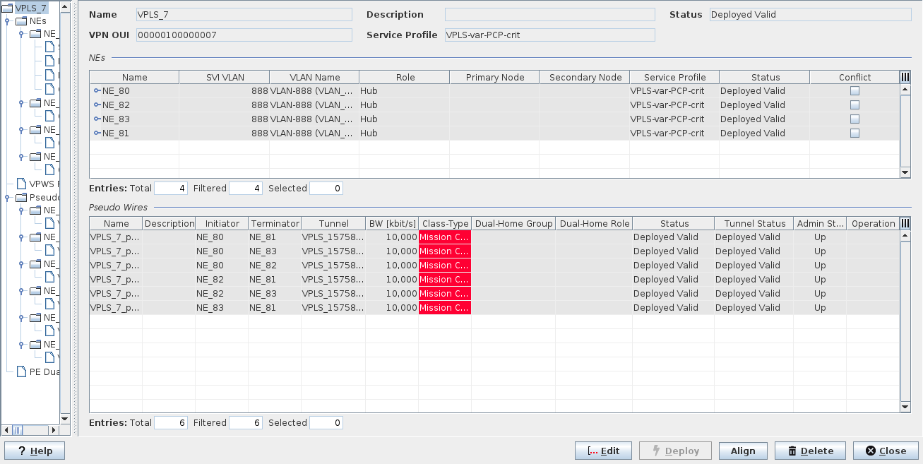
Dialog image
VPLS Service - Details
The VPLS service details dialog may look as follows (sample):
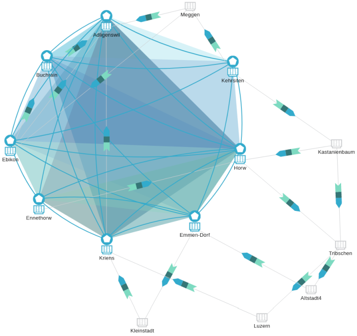
VPLS Service - Graph
The VPLS service physical graph may look as follows (sample):
Informational content
Name | The specified Name of the VPLS. |
Description | The specified Description of the VPLS. |
Status | The VPLS status: - Deploying/Removing: Display the Progress bar Indicating the current progress of deploying or deleting the selected VPLS. - Deployed Valid: The VPLS is deployed to the MPLS-TP nodes. - Deployed Invalid: One end point of the VPLS is missing or was not correctly deployed. It is saved in the FOXMAN‑UN database and is deployed to the nodes. - Saved OK: The VPLS, Pseudo Wire are saved in the database but not yet deployed in the MPLS-TP nodes. Note: If for any reason a service is invalid an “i” icon indicates additional information. You can display details on the probable cause by double-clicking on the Status field. The “i” icon only appears when the service status is invalid or unaligned. |
VPN OUI | A unique VPN id calculated by ENP, common for all member nodes of a VPLS instance. |
Service Profile | The name of the Service Profile used for creating the VPLS. |
NEs
Name | The specified Name of the NE. The NE can be expanded or collapsed to show or hide the units and ports used for the VPLS service on the NE. |
SVI VLAN / VLAN Name | The selected VLAN ID and the VLAN name of the incoming Ethernet frames of the node. |
Role | The selected Pseudo Wire binding of the node: Hub or Spoke. |
Primary Node | Applicable to Spoke NE. Displays the (primary) Hub node to which the spoke NE is connected. |
Secondary Node | Applicable to Spoke NE in case of PE Dual Homing. Displays the secondary Hub node to which the spoke NE is connected. |
Service Profile | The name of the Service Profile used for creating the VPLS. |
Status | The deployment status of the service on the NE. |
Conflict | A mark in the checkbox is set if there is a conflict occurring on the VPLS on this NE instance. Possible conflicts are inappropriate QoS settings or an inappropriate port VLAN mode. |
NEs – NE instance
Name | The specified Name of the NE. The NE can be expanded or collapsed to show or hide the units and ports used for the VPLS service on the NE. |
SVI VLAN / VLAN Name | The selected VLAN ID of the incoming Ethernet frames of the node. |
Status | The deployment status of the service on the NE. |
Binding | The selected Pseudo Wire binding of the node: Mesh or Spoke. |
Attached To NE | Applicable to Spoke NE. Displays the Mesh node the spoke NE is connected to. |
Service Profile | The name of the Service Profile used to create the VPLS. |
Status | The service status: - Deployed Valid: The Service is deployed to the MPLS-TP nodes. A deployed Service can be deleted. It can neither be modified nor set back to saved. - Deployed Invalid: One component of the service is not correctly deployed. It is saved in the FOXMAN‑UN database and is deployed to the nodes. - Saved OK: The service is saved in the database but not yet deployed in the MPLS-TP nodes. - Saved Incomplete: One side of the service is not correctly deployed. It is saved in the FOXMAN‑UN database. |
Conflict | A mark in the checkbox is set if there is a conflict occurring on a port on this NE instance. Possible conflicts are inappropriate QoS settings or an inappropriate port VLAN mode. |
NEs – NE instance – Ports
Reference | Displays the unit name, and <slot> <port>. |
Type | Displays the port mode of the port (CVP) |
VLAN Mode | Displays the VLAN mode of the port as set via the FOXCST GUI. |
PVID | Displays the Port VLAN ID of the port as set via the FOXCST GUI. |
Service Profile | The name of the Service Profile used to create the VPLS. |
Status | The deployment status of the service on the port. |
Conflict | A mark in the checkbox is set if there is a conflict occurring on this port instance. Possible conflicts are inappropriate QoS settings or an inappropriate port VLAN mode. |
NEs – NE instance – port instance
Shows properties of the selected port, including Rate Limiting parameters.
VPWS Ports
Port | Displays the Ethernet unit <slot>/<port> |
Status | The deployment status of the service on the NE. |
Attached to NE | The name of the NE to which the port is attached. |
Pseudo Wire | The name of the Pseudo Wire used for the VPWS port. |
Tunnel | The name of the tunnel used for the VPWS port. |
Pseudo Wires
Name | The specified Name of the Pseudo Wire. |
Description | The specified Description of the Pseudo Wire. |
Initiator | The name of the initiator NE. |
Terminator | The name of the terminator NE. |
Tunnel | The name of the tunnel used for the PW. |
BW [kbit/s] | The allocated Pseudo Wire bandwidth. |
Class Type | The allocated Class Type. |
Dual-Home Group | The name of the Dual-Home group to which the PW belongs. |
Dual-Home Role | The role of the PW in a Dual-Home configuration. |
Status | The Pseudo Wire status: - Deployed Valid: The Service, and Pseudo Wire are deployed to the MPLS-TP nodes. A deployed Service can be deleted. It can neither be modified nor set back to saved. - Deployed Invalid: One side of the Pseudo Wire is not correctly deployed. It is saved in the FOXMAN‑UN database and is deployed to the nodes. - Saved OK: The Service, Pseudo Wire are saved in the database but not yet deployed in the MPLS-TP nodes. - Saved Incomplete: One side of the Pseudo Wire is not correctly deployed. It is saved in the FOXMAN‑UN database. |
Tunnel Status | The Tunnel deployment status. |
Admin State | The PW Admin State; can be “Up” or “Down”. |
Operational State | The PW operational state; can be “Up” or “Down”. |
Dual Home Operational State | The PE Dual Home services operational state; can be “Up” or “Down”. |
Operation | Indicates operational states and transitions. |
Pseudo Wire and Tunnel Details
Pseudo Wire
Name | The specified Name of the Pseudo Wire. |
Description | The specified Description of the Pseudo Wire. |
Status | The Pseudo Wire status: - Deployed Valid: The Service, and Pseudo Wire are deployed to the MPLS-TP nodes. A deployed Service can deleted. It cannot be modified and set to saved Service. - Deployed Invalid: One side of the Pseudo Wire is not correctly deployed. It is saved in the FOXMAN‑UN database and is deployed to the nodes. - Saved OK: The Service, Pseudo Wire are saved in the database but not yet deployed in the MPLS-TP nodes. - Saved Incomplete: One side of the Pseudo Wire is not correctly deployed. It is saved in the FOXMAN‑UN database. |
BW [kbit/s] | The allocated Pseudo Wire bandwidth. |
Class Type | The allocated Class Type. |
Tunnel | The name of the tunnel used for the PW. |
Attachment Circuits, Initiator/Terminator
AC | The selected NE. |
Status | The Pseudo Wire status: - Deployed Valid: The Service, and Pseudo Wire are deployed to the MPLS-TP nodes. A deployed Service can be deleted. It can neither be modified nor set back to saved. - Deployed Invalid: One side of the Pseudo Wire is not correctly deployed. It is saved in the FOXMAN‑UN database and is deployed to the nodes. - Saved OK: The Service, Pseudo Wire are saved in the database but not yet deployed in the MPLS-TP nodes. - Saved Incomplete: One side of the Pseudo Wire is not correctly deployed. It is saved in the FOXMAN‑UN database. |
Type | The defined Service Type. |
AC VLAN/PW VLAN | - AC VLAN: The SVI VLAN ID which is mapped to the local VLAN ID. - PW VLAN: The Pseudo Wire VLAN ID. |
In Label | The incoming Pseudo Wire label. |
Out Label | The outgoing Pseudo Wire label. |
Binding | (Mesh or Spoke) This is usually empty for a VPWS due to the point-to-point characteristics of a VPWS. |
Selected Tunnel
Name | The specified Name of the tunnel. |
Description | The specified Description of the tunnel. |
BW [kbit/s] | The allocated tunnel bandwidth. |
Status | Indicates the Status of the tunnel: - Deployed Valid: The path is complete. The tunnel and LSP(s) are saved in the FOXMAN‑UN database and are deployed to the nodes. A deployed tunnel can be deleted. It cannot be modified nor set back to saved. - Deployed Invalid: The tunnel is incomplete, i.e. there is a hole in the path. It is saved in the FOXMAN‑UN database and is deployed to the nodes. - Saved OK: The path is complete. The tunnel and LSP(s) are saved in the FOXMAN‑UN database. A saved tunnel can be modified, deployed and deleted. - Saved Incomplete: The tunnel is incomplete, i.e. there is a hole in the path. It is saved in the FOXMAN‑UN database. |
Initiator | The name of the initiator NE. |
Terminator | The name of the terminator NE. |
Service Profile | The name of the service profile applied when creating the tunnel. This name is empty if no service profile has been used. |
Used BW [kbit/s] | The total allocated bandwidth of all configured (saved in the database) and deployed services using this tunnel. |
Working / Protection LSP | For details, please refer to section Working and Protection Label Switched Paths (LSPs) |
BFD / Path Protection | For details, please refer to sections BFD (Bidirectional Forwarding Detection) and Path Protection |
Encryption | Shows details on the Encryption parameters for Initiator and Terminator side of the tunnel: - Working Encryption Settings: Status, Profile, - Protection Encryption Settings: Status, Profile. |
Attached Pseudo Wire | For details, please refer to section Attached Pseudo Wires |
Diagnostic | Provides OAM commands such as LSP ping, trace route, and delay measurements. For details refer to Diagnostic. |
Class Type | The allocated Class Type. |
Optional entries
Not applicable.
Mandatory entries
Not applicable.
Controls (buttons, menu items, etc.)
? Help | Calls the help viewer and opens this page. |
Edit | Switches to edit mode, calls the Modify Service wizard. Note: The Modify Service wizard provides the same steps and parameters as the Create VPLS dialog. |
Deploy | Deploys the Service to the MPLS-TP nodes (not available for deployed, aligned services with status “Deployed Valid”). |
Align | Aligns the Service such that any misalignment between the ENP database configuration and the Service present in the network is corrected. |
Delete | Deletes the Service. |
Close | Closes the dialog. |
Related dialogs / windows
VPLS,