
Application (View/Create/Edit)
Purpose
An Application is a container of TE(s). It contains at least one TE. An Application dialog can be in two modes:
− View
− Edit
The View mode allows viewing the details of the Application, such as:
− the TEs contained in the Application
− the Path(s) and Specific Data, and a-end/z-end TP properties of the selected TE
− likewise, it allows you to cut TE(s) to be pasted to another Application.
The Edit mode allows creation of new Application and modification of an existing application, such as:
− Creating/Modifying/Deleting TE(s)
− Adding existing TE(s) from other Application(s) via Paste function.
− Routing (Path selection) of the selected TE
The user of the Application Edit mode is listed in the Application Manager List.
The Application dialog to create new Application is called from the NP Main Window menu: File > New Application.
The dialog to view or edit an existing Application is called from the NP Main Window’s Application context menu > Details.
Dialog image
Application – [Name]
Mandatory entries
Not applicable.
Optional entries
Not applicable.
Informational content
− Details of all the Transport Entities contained in the selected Application.
− Working/Protecting Path and Specific Data details of the Selected Transport Entity, as listed below:
Working Path/Protecting Path | |
Type | Shows a list of the path elements. A path element can be a: - Hole, represents a missing piece in the path. - MC (Matrix Connection), on board cross connection. - LC (Link Connection), a section between nodes. - SNC (subnetwork circuit). |
Status | Indicates the availability status of the selected TE: - Valid, The FOXMAN‑UN NP Managed Object is fully supported by resources in the network. - Waiting, The FOXMAN‑UN NP Managed Object is fully defined and scheduled for a later time,e.g. configuration has yet to be committed (downloaded) to the network. - Invalid, No resources in the network support the Managed object. - Based Invalid, The FOXMAN‑UN NP Managed Object is based on other NP Managed Object with availability status set to invalid. - Incomplete, The FOXMAN‑UN NP Managed Object is partially but not fully defined, e.g. part of the route is missing or unspecified. - Based Incomplete, The Managed Object is based on other FOXMAN‑UN NP Managed Object with availability status set to incomplete. |
Name | Name of the Transport Entity |
a End TP/z End TP: | Details of the Circuit (or Trail) End Points |
Channel | Channel/TS or bytes used to carry the Circuit or Trail |
Protection | Shows the path protection mode of the Application possible entries are: - LTP, SNC/I,SNC/P, - No Protection. |
Topological | Indicates if the Trail is “Topological”, i.e. if its extremities are linked with a cable (electrical or optical). |
Fixed | Indicates that the MC cannot be deleted. |
Specific Data | |
The Specific Data are: - LCs used by and some details of those LCs, in case of a trail; - TE Name and Used by, in case of a SNC; - End point info and circuit info for a circuit. |
Controls (buttons, menu items, etc.)
Edit (Application View Mode)
Details A End TP/Details Z End TP | Calls the TTP Trail Termination Point dialog of the selected TE, which displays the details of the A End TP/Z End TP. | |
Cut |  | Allows you to cut TE(s) into another Application. Activated only in View mode. |
Paste |  | Allows you to paste one or more TEs from another Application. Activated only in Edit mode. |
Conflict State |  | When grayed out, no TE editing conflict is present. When colored orange, there is a conflict of simultaneous TE editing by two users. |
Edit (Application Edit Mode)
 | Calls the New TE dialog to create new Transport Entity (TE). | |
 | Calls the Modify TE dialog to edit the selected Transport Entity. | |
Delete TE |  | Calls the Confirm delete dialog to confirm the deletion of the selected TE(s). |
Set Main TE | Set the selected TE as the main TE. The main TE is marked bold in the TE list. The main TE is shown in the NP Main Window allowing the user to give information about the application. | |
Calls the TTP dialog of the selected TE, which displays the details of the A End TP/Z End TP. | ||
Show NP Usage… | Opens a dialog to show information on the usage of NP transport entities, see NP Usage. | |
Refer to Working/Protecting Path context menu. |
Help
? Help | Calls the help viewer and opens this page. |
Filter Area
Name | This specifies the name of the Application. Similar to TE Name in the TE Information mask. It is possible to add a new self explanatory name. The format of the auto generated name is: “A_”+NUMBER+SPACE+DATE+SPACE+TIME It is a label for information text string of longer than 64 characters (can also be an empty string) that can be associated with Transport Entity described in the Main Window. this can be used by the operator to provide descriptive information about the TE. The NP TE Name can be entered at the time the new TE is created. |
Status | Displays the state of the Application. It indicates if the Application is established and running. This field cannot be edited. The entries in the status field can be: - Valid: The NP managed object is fully supported by resources in the network. - Waiting: the NP managed object is fully defined and scheduled to be downloaded later in the network. - Invalid: the NP managed object is not supported by some resources in the network. - Based Invalid: the NP managed object is based on other application with invalid state. - Incomplete: the NP managed object is not fully defined and cannot be scheduled for download. - Based Incomplete: the NP managed object is based on other application with incomplete state. |
Service | Specifies the type of service assigned to a TE in an Application. For example Service 1 can be Voice, Service 2 can be Data and Service 3 can be ISDN etc. By default there is Service 1 to 3 defined. The number of services can be enhanced by adapting the parameter “np_service_values_list” of the file $NEM_HOME/etc/np.conf. |
Edit button
Edit | Changes the dialog to Edit Mode. Allows: - Creation of new TE, - Modify TE, - Delete TE. |
Transport Entities Context Menu
Refer to Edit menu (Application View /Edit). |
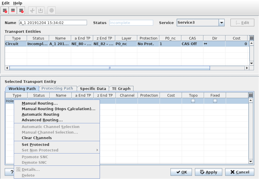
Working/Protecting Path Context Menu
Manual Routing | Calls the Manual Routing: Next Hop List dialog to search for all possible hops having enough capacity for the service to be routed. The user can select one of these hops. NP search then for all possible hops from the selected hop. |
Manual Routing (Hops Calculation) | Calls the Manual Routing: Next Hop List dialog to search for all possible hops having enough capacity for the service to be routed with the additional indication of minimum number of hops to reach the final. The user can select one of these hops. The NP search then for all possible hops from the selected hop. |
Automatic Routing | Enables the route completion in one operation based on the values specified in the Set Auto Routing Parameters dialog. |
Advanced Routing… | Select parameters before executing the routing process. The parameters are the same as in the Set Auto Routing Parameters dialog but are applied directly when clicking on “Route”. You can either “Route” with the parameters set in the dialog, or “Abort”. |
Automatic Channel Selection | Selects a channel automatically. Note: Once routed, the Circuit knows on which hops the End-to-End signals are multiplexed. The next step is to select a dedicated TS in all Trails of the Path. |
Manual Channel Selection | Calls the Select Possible Channels dialog, which displays a list of all possible channels to choose from. |
Clear Channels | Clear the channels from the path elements. |
Set Protected | Add protection to the TE. The path has to be build before TE gets valid or waiting. |
Set Non Protected | Choose between Keep Working or Keep Protecting Path. The chosen path is used as working path. |
Promote SNC | The SNC is removed from the TE list and replaces the SNC with the original MC to MC (e.g. MC-LC-MC…MC) path sequence. |
Demote SNC | Paths from MC to MC can be defined as SNC. This adds the SNC in the TE list. |
Details | Calls the Application Trail View. |
Delete | Delete the path elements. Holes cannot be deleted. |
TE Graph
Shows the graphical representation of the selected TE as described in TE Graph Tab. This tab is not available during creation of a new application, but only with at least one existing TE. |
Specific Data Context Menu
This field is used to allocate specific information to the Endpoint of a TE.
e.g. for a TE based on a Circuit:
To change the default attributes of the Endpoint Info and Circuit Info: /opt/nem/etc/np.conf
#np_circuit_data_fields Data1;Data2;Data3
#np_circuit_ep_data_fields EPData1;EPData2
It is recommended to do the definition during the commissioning process of NP.
Furthermore, in the settings file “/opt/nem/etc/np.conf” a Path Cost Calculation Model can be chosen. The three options available are:
• Model 1: (CostWorking + CostProtecting)
• Model 2: (CostWorking + CostProtecting) / 2
• Model 3: (CostWorking * CostProtecting) / (CostWorking + CostProtecting)
The parameter “path_cost_calc_model” can be set to 1, 2, or 3. Default is 1, but by default the parameter is disabled. To enable the parameter, remove the # in front of the entry.
? Help | Calls the FOXMAN‑UN help viewer and opens this page. |
OK | Applies the modifications and closes the dialog. |
Apply | Applies the modifications without closing the dialog. |
Cancel | Closes the dialog without applying the modifications. |
Table Sorting and Filtering/Export and Printing
Please refer to Table Sorter section for details.
Related dialogs/windows
NP Main Window,