
VPWS Details
Purpose
The VPWS dialog in view mode displays the VPWS, the Pseudo Wire, and the selected tunnel in one view.
It provides a “VPWS Service - Details” tab and a “VPWS Service - Graph” tab.
Details
The “Details” tab provides the following types of information for the VPWS as described in detail further below:
• General,
• Attachment Circuits,
• Quality of Service
• Rate Limiting.
Graph
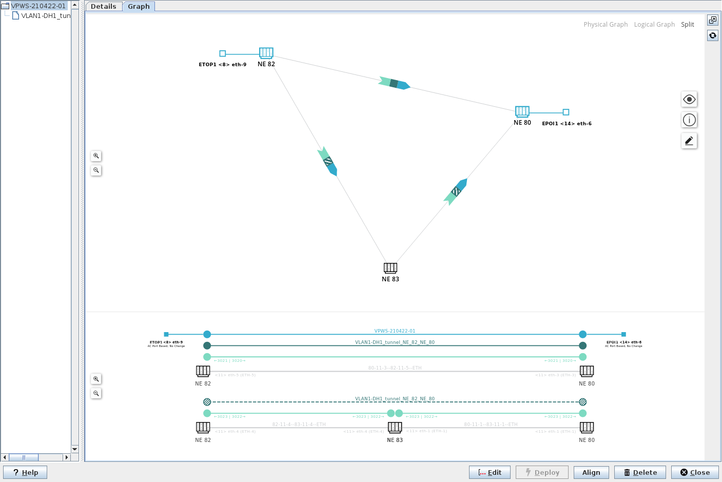
The “Graph” tab provides a graphical presentation of the physical and/or the logical view on the service.
Depending on the dialog window size you can select the physical graph, the logical graph, or a split view with both the physical and the logical graph shown.
The physical graph of the VPWS shows involved initiator, transit, and terminator NEs (nodes), service access points, and links. It also indicates the different layers (service, Pseudo Wire, tunnel, link) with colors.
The logical graph of the VPWS shows the logical layers used to provide the service. It uses the same colors for showing the different layers (service, Pseudo Wire, tunnel, link) as the physical graph does.
Working and protecting LSPs (tunnels) are shown as solid lines and patterns (working tunnel) and dotted line and patterns (protecting tunnel), respectively.
VPWS Graph Symbols
The following icons or patterns are used in the graph:
Icon or Pattern | Description |
|---|---|
NE symbol with NE name. | |
NE with attachment circuit (AC), NE name and AC unit, slot, and port. | |
Link, section (selected). | |
Link, VLAN sub-interface (selected). | |
Layers of a section (default) with PW, tunnel LSP link. | |
Layers of a section (‘show all layers’ enabled) with service, PW, tunnel, LSP, LSP link, link. |
View Options:
Several view options can be enabled or disabled in the graph via the view icon  :
:
Paths:
• Working Path,
• Protection Path,
View Settings:
• Show All Layers,
• Show Alarms,
Labels:
• Show TE labels,
• Show Shared Resource Count,
• Show NE IDs.
Legend:
In the View Options - Legend, the colors used in the diagram are assigned to the layers. A click on the specific color icon will highlight or fade out the layer, respectively. The following layers are available for highlighting or fading out:
• Layers:
− Service,
− Pseudo Wire,
− Tunnel,
− LSP,
− LSP Link,
− Link,
• Physical:
− Section.
Issues
A list of possible issues can be opened/closed via the info icon  . It includes information related to shared resources, status, holes, alarms.
Edit Mode
The graph can be edited which allows the user to rearrange the NEs (nodes) in the physical graph.
The icon for starting the edit mode is  . The icon is colored dark blue while the edit mode is active. To go back to view mode, select “Stop Editing Mode”.
Further options of the graphical view:
• Zoom in / zoom out;
• Open in a separate window;
• Refresh;
• Reset layout - resets the physical graph to the default view.
Dialog image
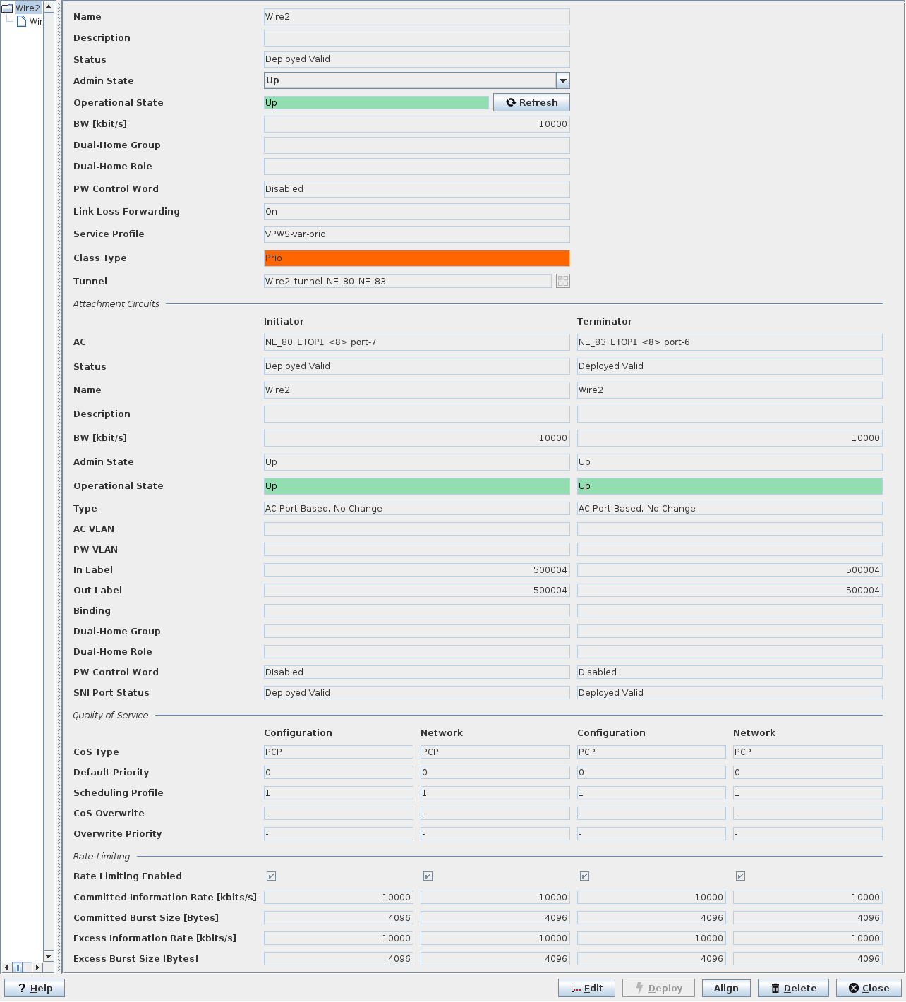
VPWS Service - Details
VPWS Service - Graph
Informational content - Details tab
Name | The specified Name of the Service. |
Description | The specified Description of the Service. |
Status | The Pseudo Wire status: - Deployed Valid: The Service, and Pseudo Wire are deployed to the MPLS-TP nodes. A deployed Service can be deleted. It can neither be modified nor set back to saved. - Deployed Invalid: One side of the Pseudo Wire is not correctly deployed. It is saved in the FOXMAN‑UN database and is deployed to the nodes. - Saved OK: The Service, Pseudo Wire are saved in the database but not yet deployed in the MPLS-TP nodes. - Saved Incomplete: One side of the Pseudo Wire is not correctly deployed. It is saved in the FOXMAN‑UN database. |
Admin State | The admin state can be set to “Up” or “Down”. When opening the dialog, the current admin state is shown. |
Operational State | The current VPWS operational state; when up, the field background is colored green. When down, the field background is colored orange. |
BW [kbit/s] | The allocated Pseudo Wire bandwidth. |
Dual-Home Group | The name of the Dual-Home group to which the PW belongs. |
Dual-Home Role | The role of the PW in a Dual-Home configuration. |
PW Control Word | Indicates whether the PseudoWire Control Word is enabled or disabled. |
Service Profile | The allocated Service Profile. |
Class Type | The allocated Class Type. |
Tunnel | The allocated tunnel name. |
Attachment Circuits, Initiator/Terminator
AC | The Initiator/Terminator Attachment Circuit. The expression consists of NE name, unit name, slot number, and port number. |
Status | The Pseudo Wire status: - Deployed Valid: The Service, and Pseudo Wire are deployed to the MPLS-TP nodes. A deployed Service can be deleted. It can neither be modified nor set back to saved. - Deployed Invalid: One side of the Pseudo Wire is not correctly deployed. It is saved in the FOXMAN‑UN database and is deployed to the nodes. - Saved OK: The Service, Pseudo Wire are saved in the database but not yet deployed in the MPLS-TP nodes. - Saved Incomplete: One side of the Pseudo Wire is not correctly deployed. It is saved in the FOXMAN‑UN database. |
Name | The specified Name of the Service. |
Description | The specified Description of the Service. |
BW [kbit/s] | The allocated Pseudo Wire bandwidth. |
Admin State | Shows the AC admin state (“Up” or “Down”). |
Operational State | The current VPWS operational state at the Initiator and Terminator ends; when up, the field background is colored green. When down, the field background is colored orange. |
Type | The defined Initiator/Terminator Type. |
AC VLAN/PW VLAN | The defined Attachment Circuit/Pseudo Wire VLAN. |
In Label | The incoming Pseudo Wire label. |
Out Label | The outgoing Pseudo Wire label. |
Binding | (Mesh or Spoke) This is usually empty for a VPWS due to the point-to-point characteristics of a VPWS. |
Dual-Home Group | The name of the Dual-Home group to which the PW belongs. |
Dual-Home Role | The role of the PW in a Dual-Home configuration. |
PW Control Word | Indicates whether the PseudoWire Control Word is enabled or disabled. |
SNI Port Status | The deployment status of the SNI port on Initiator/Terminator. |
Quality of Service,
Initiator (Configuration, Network)/Terminator (Configuration, Network)
Initiator (Configuration, Network)/Terminator (Configuration, Network)
If there is a misalignment between the network/node(s) and the configuration in the ENP database, the misaligned settings are marked and can be aligned via the “Align” command button.
CoS Type | The Class of Service Type configured on Initiator/Terminator side. |
Default Priority | The Default Priority configured on Initiator/Terminator side. |
Scheduling Profile | The Scheduling Profile applied on Initiator/Terminator side. |
CoS Overwrite | The CoS overwrite mode: - Overwrite, - Maintain, as defined during service creation. |
Overwrite Priority | The overwrite priority for the service as defined during service creation. |
Rate Limiting,
Initiator (Configuration, Network)/Terminator (Configuration, Network)
Initiator (Configuration, Network)/Terminator (Configuration, Network)
If there is a misalignment between the network/node(s) and the configuration in the ENP database, the misaligned settings are marked and can be aligned via the “Align” command button.
Rate Limiting Enabled | Indicates whether Rate Limiting is enabled or not. |
Committed Information Rate [kbits/s] | Shows the configured Committed Information Rate (CIR) in kbit/s. |
Committed Burst Size [Bytes] | Shows the configured Committed Burst Size (CBS) in Bytes. |
Excess Information Rate [kbits/s] | Shows the configured Excess Information Rate (EIR) in kbit/s. |
Excess Burst Size [Bytes] | Shows the configured Excess Burst Size (EBS) in Bytes. |
Tunnel Details
See Tunnel Details section.
Optional entries
Not applicable.
Mandatory entries
Not applicable.
Controls (buttons, menu items, etc.)
Edit | Switches to edit mode, calls the Modify Service wizard. Note: The Modify Service wizard provides the same steps and parameters as the Create VPWS dialog. |
Deploy | Deploys the Service to the MPLS-TP nodes (not available for deployed, aligned services with status “Deployed Valid”). |
Align | Aligns the Service such that any misalignment between the ENP database configuration and the Service present in the network is corrected. |
Delete | Deletes the Service. |
Close | Closes the dialog without applying the changes. |
? Help | Calls the help viewer and opens this page. |
Related dialogs / windows
VPWS,