
Create VPLS
The “Create VPLS” wizard is started with the “+ Create” button from the ribbon of the VPLS tab in the MPLS-TP Map.
The “Modify VPLS” wizard is started for a selected VPLS with the “Modify VPLS” button from the action menu of the selected VPLS.
Please note:
A VPLS can be modified using the command “Modify VPLS”. This command will open the “Modify VPLS: <VPLS Name>” wizard, which provides the same steps as the “Create VPLS” wizard, but with some restrictions regarding modification of settings, i.e., not all parameters can be modified.
The wizard leads you through 6 basic steps of creating a new VPLS in your MPLS-TP network.
The steps below show the creation of a sample VPLS,
− for creating an E-Tree VPLS, see Create E-Tree over VPLS,
− for creating a standard VPLS, continue here,
Step 1: General
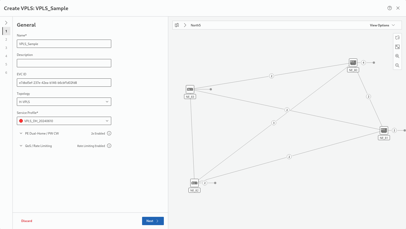
This step requires at least a unique name for the new VPLS and an appropriate service profile before proceeding to the next step.
The service profile is used to define the “PE Dual-Home / PW CW” and “QoS / Rate Limiting” settings. The description is optional; the EVC ID is generated automatically.
Under “Topology”, select either of the two options, as required:
• H-VPLS,
• E-Tree over VPLS.
This description continues for the option “H-VPLS”. For the option “E-Tree over VPLS” refer to Create E-Tree over VPLS.
The map on the right hand side shows the progress through all steps.
Click “Next >” to proceed to step 2 for H-VPLS creation.
Step 2: Endpoints
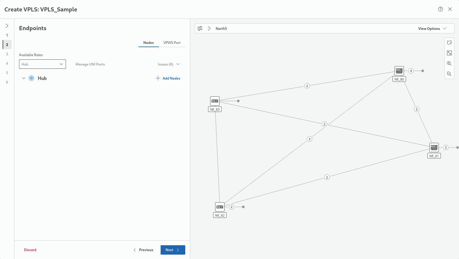
This steps requires network nodes as endpoints. The “Nodes” selector (top right in the settings area of this step) is active by default. By default, only the “Hub” role is enabled under “Available Roles”. Other roles can be enabled at any time. For selecting the appropriate nodes, click on the “+ Add Nodes” button.
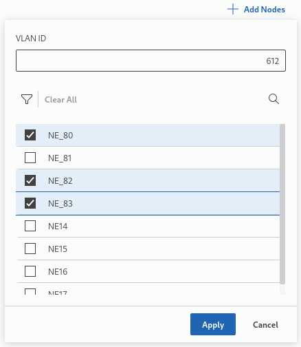
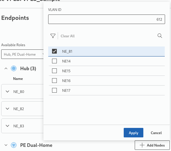
This will provide
• a field to enter the service VLAN ID,
• a list of selectable nodes, and
• a dropdown field to select from available node roles.
The available node roles depend on the service profile chosen in step 1.
Upon clicking “Apply”, the end points appear under the selected node role, in this sample under “Hub”:
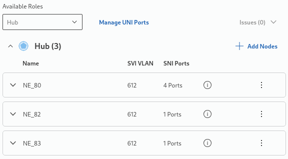
The “hub” part of the service is now also shown on the right-hand side map.
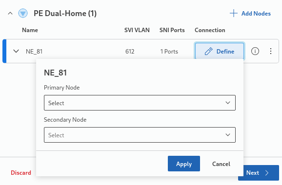
To add nodes with other roles, click again on “+ Add Nodes”. In this sample, a fourth node is added as “PE Dual Home” node:
When applied, the node is added under its role (in this sample under “PD Dual Home”) and requires more settings; in this case a “Primary Node” and a “Secondary Node”:
In case of selecting the node role to be “Spoke”, its “Primary Node” needs to be selected and applied.
When applied, the final endpoints settings are listed and also shown on the map:

The node role, VLAN ID and VLAN name can be modified at any time before proceeding via the three-dots action menu for the defined nodes.
More information on the node(s) is provided either via the “information” icon  or by expanding/collapsing the field via the down/up arrows
  for the node or for the node role.
To add VPWS ports, click on the “VPWS Port” selector, then click on the “+ Add VPWS Port” button. Select or edit the parameters
• NE,
• VPWS Type,
• AC VLAN (optional),
• PW VLAN (optional),
• Port (the port can be edited if required),
• Attached To,
then click “Apply” to add the port. Repeat the step to add more ports if required.
Click “Next >” to proceed to step 3.
Step 3: Rate Limiter
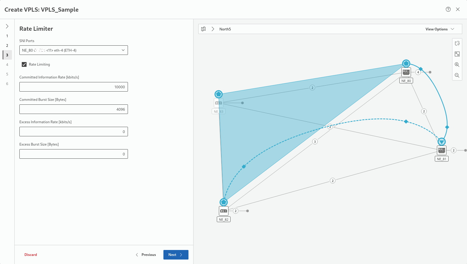
In this step, rate limiter settings are required. You can accept the settings given by the service profile or select individual settings per selected SNI port. Depending on the selected service profile, some of the settings are fixed and cannot be changed here.
Click “Next >” to proceed to step 4.
Step 4: Pseudo Wires
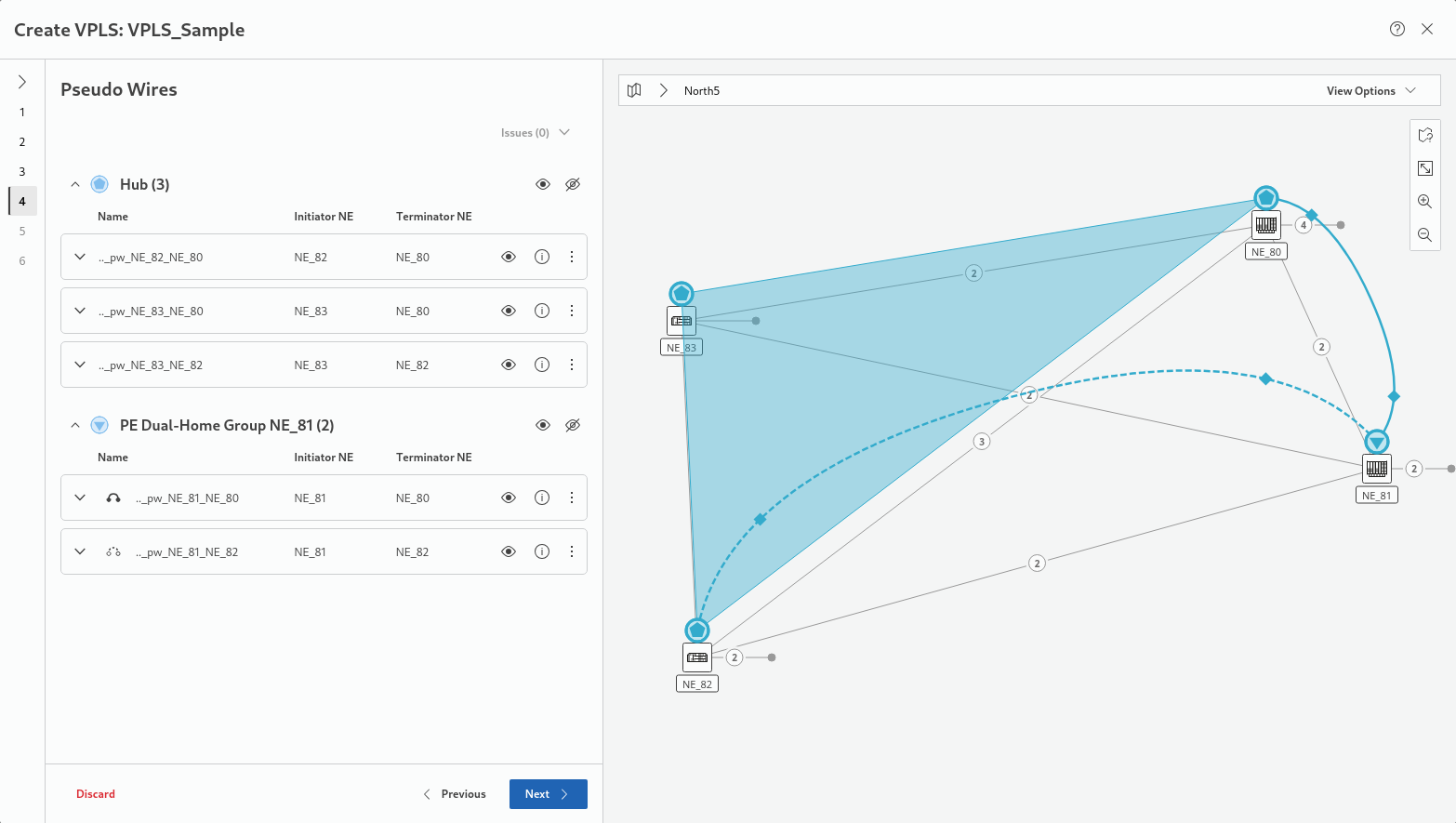
This steps shows the selected Pseudo Wires grouped by node role. You can show or hide a Pseudo Wire on the map by clicking on the show or hide icons  .
.
Properties of a specific Pseudo Wire can be modified via the three-dot action menu entry “Modify Pseudo Wire”.
More information on the Pseudo Wires is provided via the “information” icons .
Click “Next >” to proceed to step 5.
Step 5: Tunnels
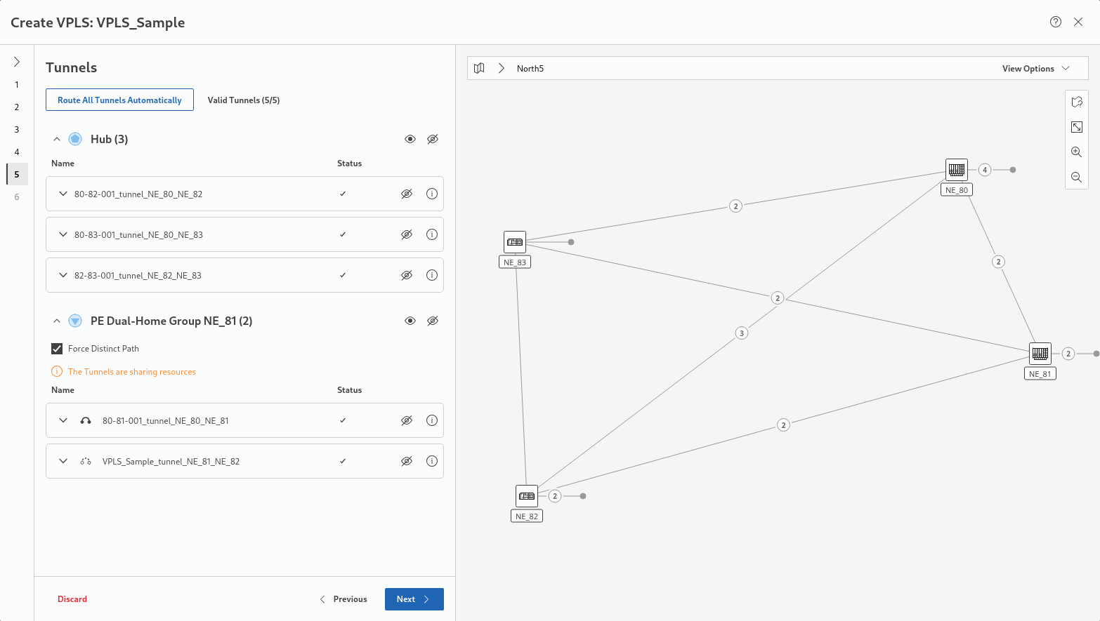
This step proposes tunnels to be assigned for the service. If no suitable tunnels exist, tunnels can be created. The button “Route All Tunnels Automatically” executes an automatic routing for all incomplete tunnels of the service. You can show or hide assigned tunnels on the map by clicking on the show or hide icons .
More information on a specific tunnel and additional settings, such as
• Protection options,
• Deployment status,
• Initiator and terminator NEs,
• Selected section / link,
is obtained by expanding/collapsing the tunnel field via the down/up arrows . When expanding a tunnel field, its visibility is automatically set to “show”. The expanded tunnel fields provide all tools to finally select appropriate tunnels for the new service, and to route the tunnel manually.
For protected tunnels, make sure both working and protecting tunnels are routed.
Once all tunnels show an OK mark in the Status column the step is completed.
Click “Next >” to proceed to step 6.
Step 6: Summary
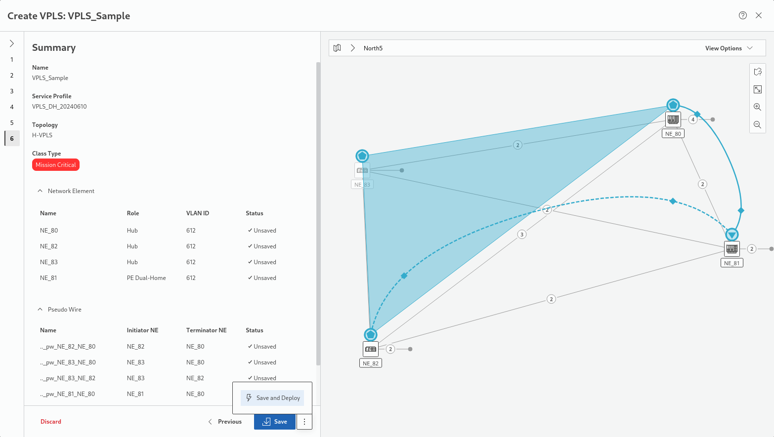
This step shows a summary of the relevant settings related to General, Network Element, and Pseudo Wire properties. The respective fields can be expanded/collapsed via the down/up arrows .
Once the service settings are verified, either
• click the “Save” button to execute a save action for the service and its components or
• click the three-dots menu button right to it and execute “Save and Deploy” to save and deploy the new service and its components to the network.
In both cases, progress and status are shown.
Click “Finish” to close the wizard and return to the MPLS-TP Map view.