Create E-Tree over VPLS
For more detailed information and samples of supported E-Tree creation scenarios, also refer to the application note “E-Tree Application Scenarios” [1MRC000134] included in the FOXMAN‑UN documentation package.
The “Create VPLS” wizard is started with the “+ Create” button from the ribbon of the VPLS tab in the MPLS-TP Map.
Step 1: General
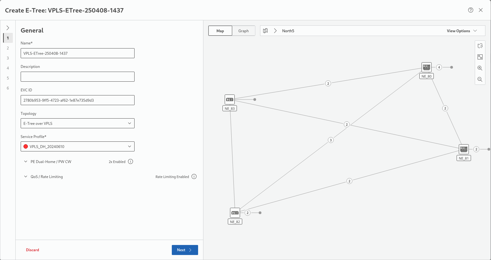
Mandatory fields are:
• Name
Mandatory selections are:
• Topology = E-Tree over VPLS
• Service Profile, requires a service profile suitable for creation of an E-Tree.
This description continues for the option “E-Tree over VPLS”. For the option “H-VPLS” refer to Create VPLS.
The map on the right hand side shows the progress through all steps. In the map header, left of the map selector drop-down menu, click either the “Map” or the “Graph” button to switch between map view and specific E-Tree graph view.
Click “Next >” to proceed to step 2 for E-Tree creation.
Step 2: Endpoints
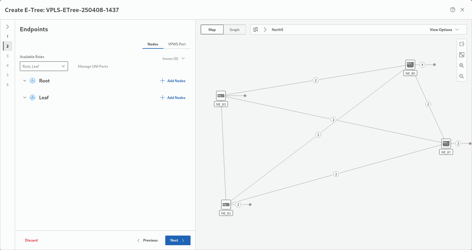
This step requires network nodes as endpoints. The “Nodes” selector tab (top right in the settings area of this step) is active by default. Under “Available Roles”, Root and Leaf are enabled by default. For selecting the appropriate Root node(s), click on the “+ Add Nodes” button.
The “Add Nodes” pop-up dialog will provide
• a field to enter the service VLAN ID,
• a list of selectable nodes.
The available node roles depend on the service profile chosen in step 1.
Select the “Root” node:
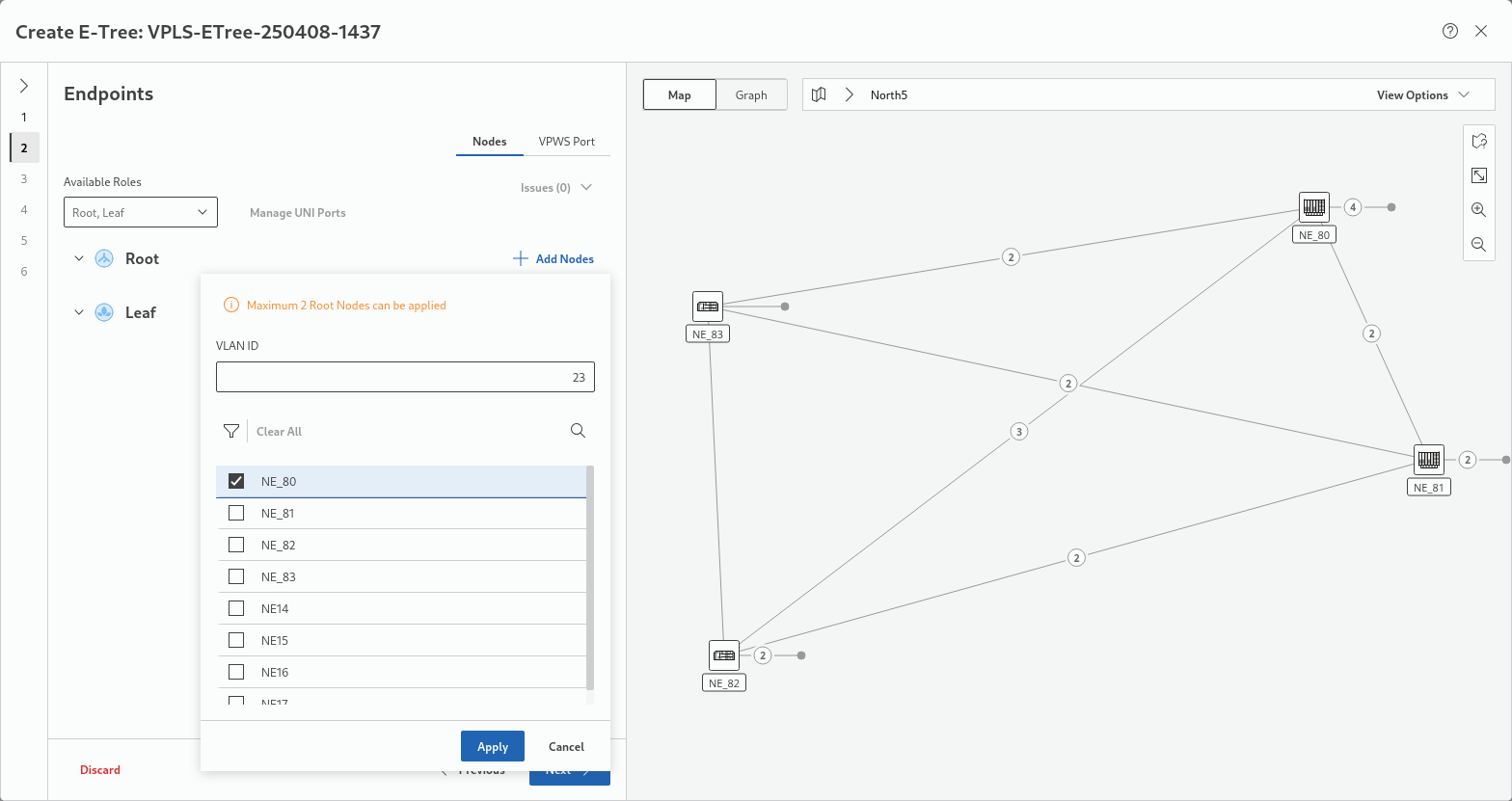
• enter the VLAN ID,
• enable the required E-Tree root node(s). In this example, node “NE_80” is selected as root node,
• Click “Apply”.
The selected root node(s) will be listed under the “Root” node category.
To manage UNI ports for the root node(s), click on the “Manage UNI Ports” tab. This will open the list of attached SNI ports of the selected node and reconfigure them as appropriate.
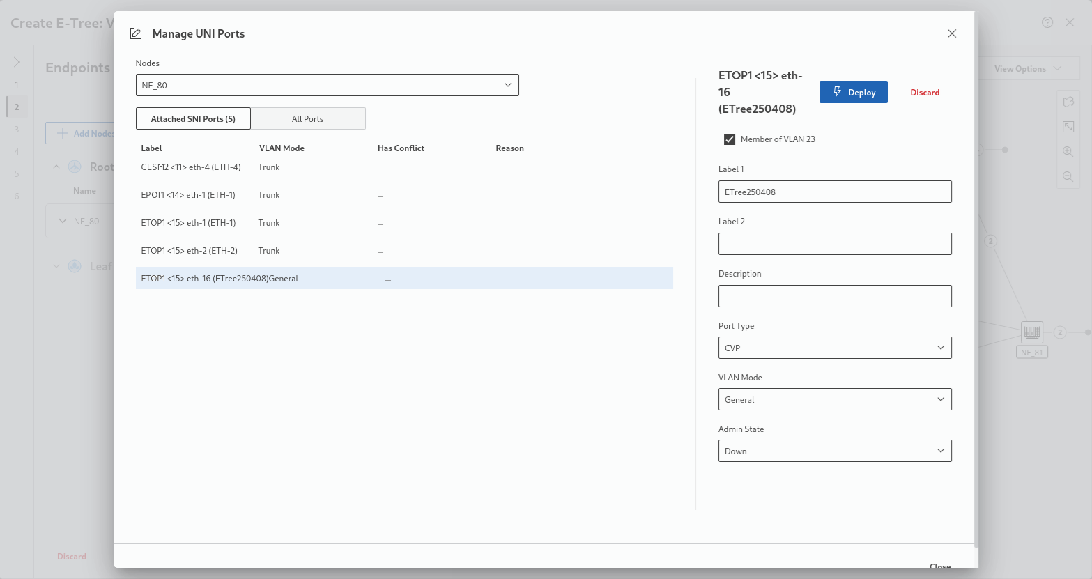
Deploy required port configuration changes to the node by clicking on “Deploy” in the header area of the port settings in the details panel of the selected port. When done, click on “Close” in the bottom right corner of the “Manage UNI Ports” dialog.
When done with adding Root nodes and managing UNI ports, continue with adding Leaf nodes. If you also need Hub nodes, enable the “Hub” category under “Available Roles”:
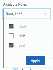
and click “Apply”.
For the Leaf and Hub nodes, proceed in a similar way as for the Root nodes, as required, to build the wanted E-Tree.
In this example, three Leaf nodes, NE_81, NE_82, NE_83, are added to the E-Tree in addition to the already selected Root node:
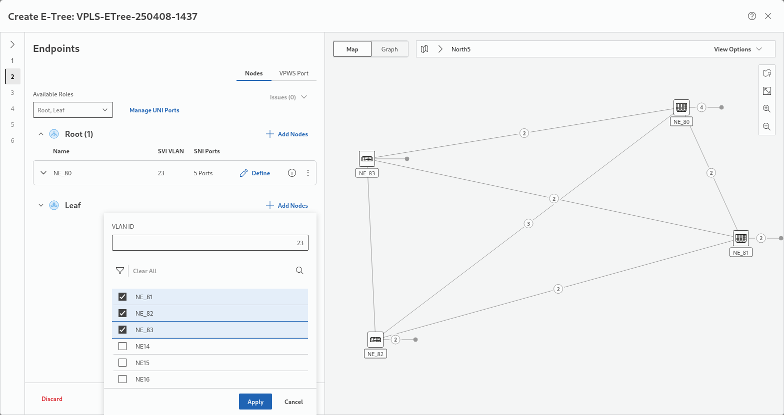
When done with adding Leaf and/or Hub nodes and managing UNI ports, apply the changes for the Leaf and/or Hub nodes by clicking “Apply” at the bottom of the selection dialog.
This will provide the overview on the selected nodes:
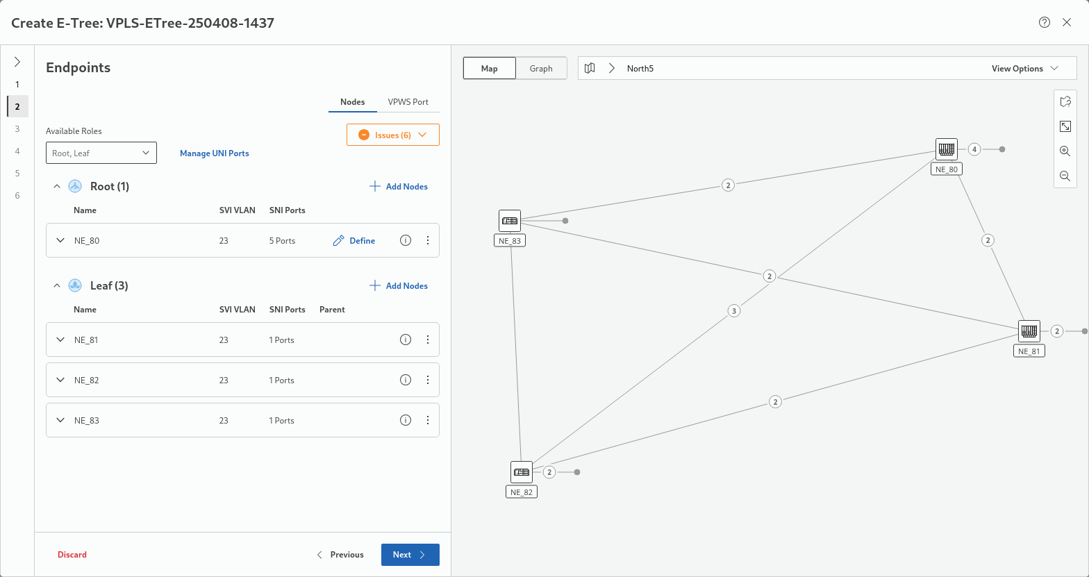
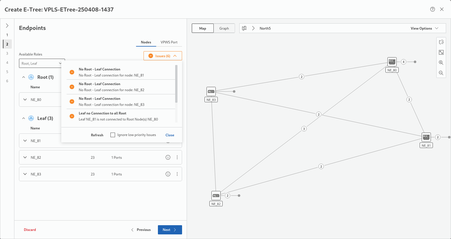
As the relations (connections) between root and leaf nodes are not yet defined, the Issues drop-down box will be marked as shown in the sample above, indicating the number of issues found. In the example it shows Issues (6).
Expand the drop-down box to view the details as shown in the next sample screenshot:
In this example, there are no root-leaf connections yet. Therefore, open the individual nodes’ fields by clicking on the expand arrow left of the node name as shown below for the node “NE_81”. This node doesn’t have a parent NE as it is not connected to the “Root” node, see “Parent Missing” marked red:
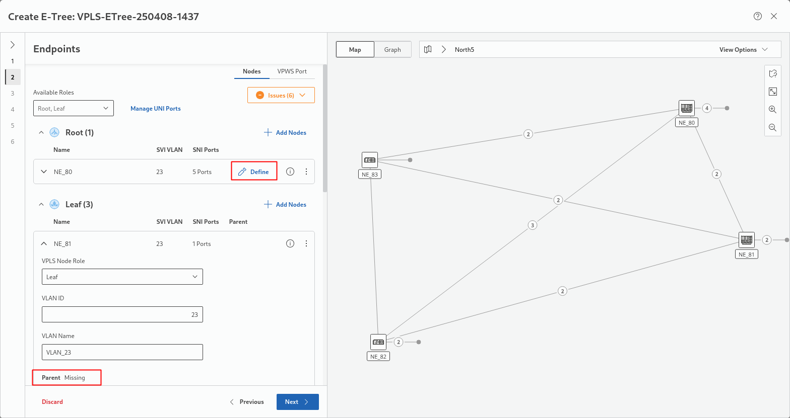
To correct this, click on the “Define” command, marked red, of the “Root” node (in this example: NE_80) and select the three leaf nodes for their “Leaf” role:
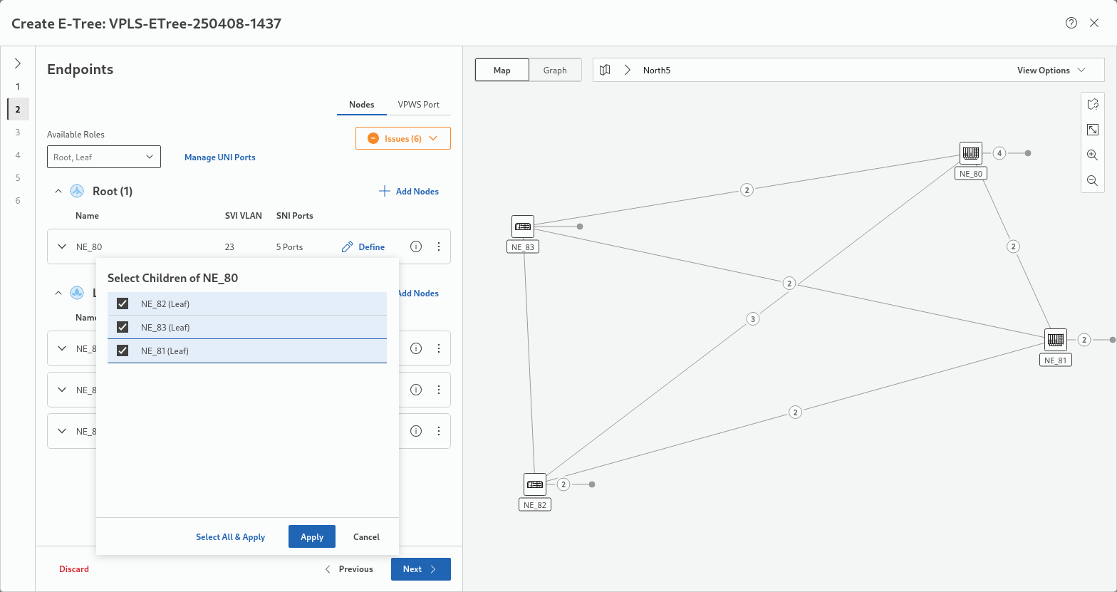
When done, apply the role selection by clicking on the “Apply” button. This will return you to the node list with the root-leaf connections shown on the map:
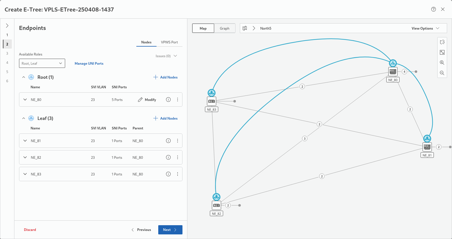
Click “Next >” to proceed to step 3.
Step 3: Rate Limiter
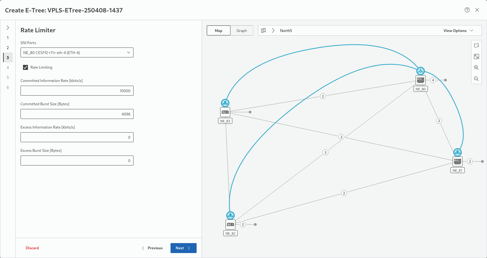
In this step, rate limiter settings are required. You can accept the settings given by the service profile or select individual settings per selected SNI port. Depending on the selected service profile, some of the settings are fixed and cannot be changed here.
Click “Next >” to proceed to step 4.
Step 4: Pseudo Wires
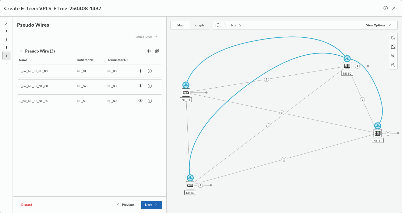
This step lists existing Pseudo Wires (PWs) chosen for the service. If no suitable PWs are available, they need to be created. You can show or hide a Pseudo Wire on the map by clicking on the show or hide icons  .
.
More information on the PWs is provided via the “information” icons  .
.
Issues with existing PWs are indicated in the “Issues” drop-down box which can be expanded to view details.
The three-dot menu provides commands to modify or delete PWs.
Click “Next >” to proceed to step 5.
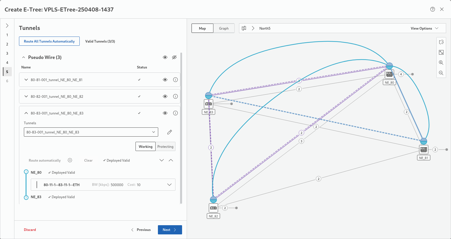
Step 5: Tunnels
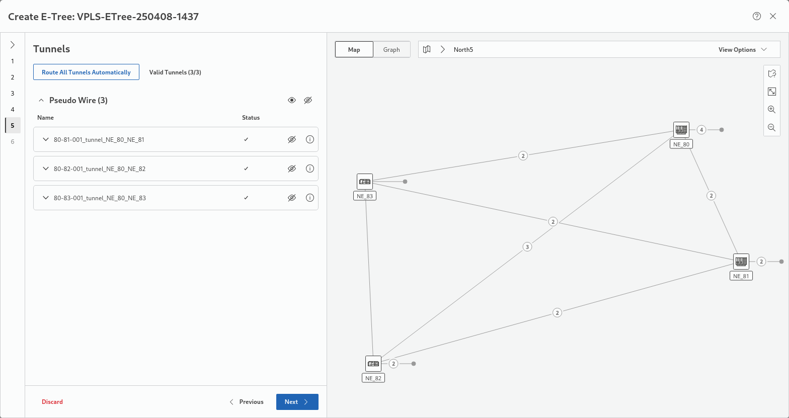
This step proposes tunnels to be assigned for the service. If no suitable tunnels exist, tunnels can be created. The button “Route All Tunnels Automatically” executes an automatic routing for all incomplete tunnels of the service. You can show or hide assigned tunnels on the map by clicking on the show or hide icons .
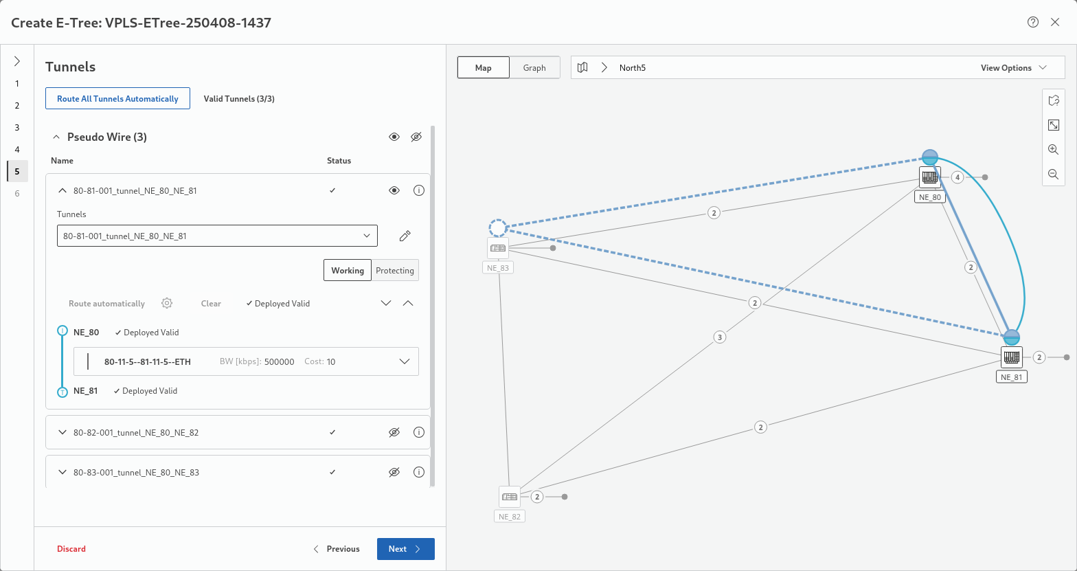
More information on a specific tunnel and additional settings, such as
• Protection options,
• Deployment status,
• Initiator and terminator NEs,
• Selected section / link,
is obtained by expanding/collapsing the tunnel field via the down/up arrows  . When expanding a tunnel field, its visibility is automatically set to “show”. The expanded tunnel fields provide all tools to finally select appropriate tunnels for the new service, and to route the tunnel manually.
For protected tunnels, make sure both working and protecting tunnels are routed. With only one of several involved tunnels shown, the map looks like shown below:
With all tunnels shown involved in this example, the map looks as below:
Once all tunnels show a OK mark in the Status column the step is completed.
Click “Next >” to proceed to step 6.
Step 6: Summary
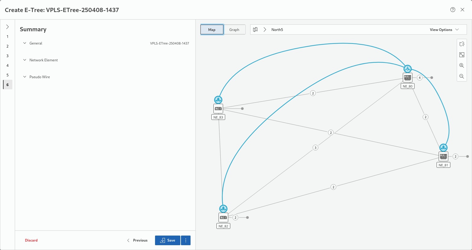
This step shows a summary of the relevant settings related to General, Network Element, and Pseudo Wire properties. The respective fields can be expanded/collapsed via the down/up arrows .
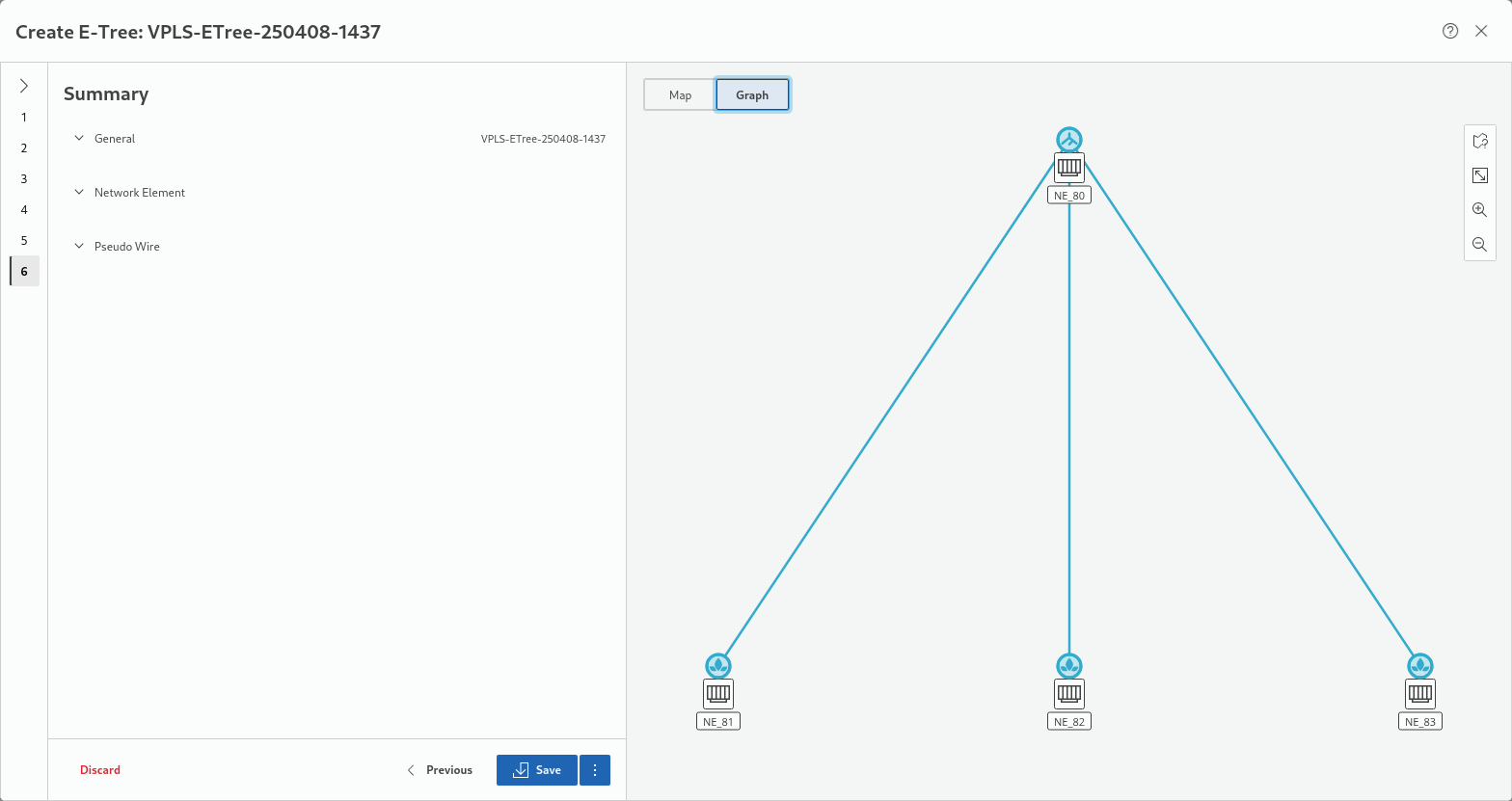
When activating the “Graph” view instead of the “Map” view the service will be shown in a specific E-Tree graph:
Once the service settings are verified, either
• click the “Save” button to execute a save action for the service and its components or
• click the three-dots menu button right to it and execute “Save and Deploy” to save and deploy the new service and its components to the network.
In both cases, progress and status are shown.
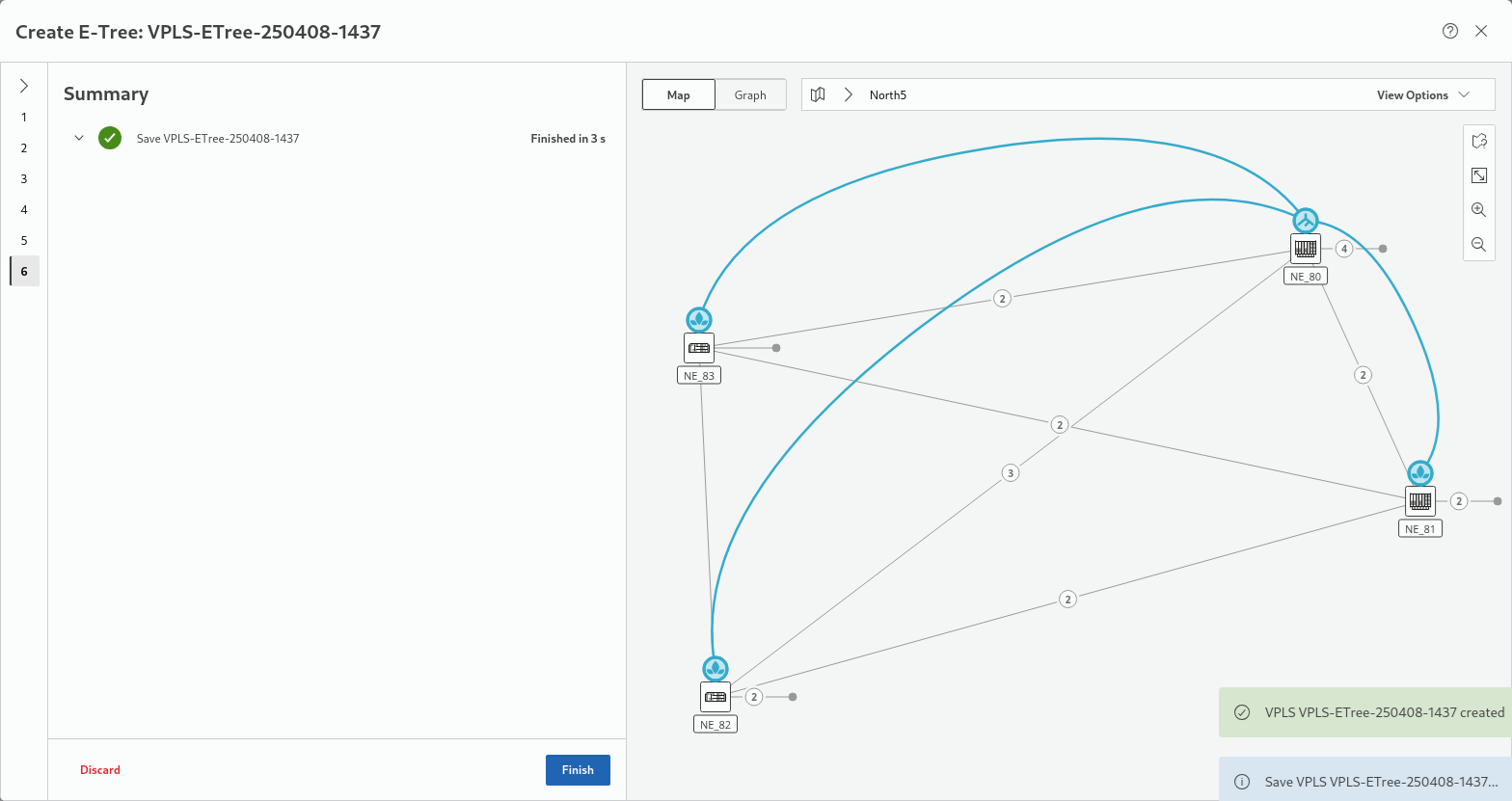
Click “Finish” to close the wizard and return to the MPLS-TP Map view.
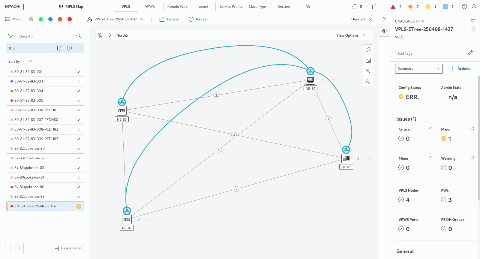
The new service will now be shown in the map: