
Create a Virtual Private LAN Service (VPLS)
The Virtual Private LAN Service (VPLS) is set up by first creating a switching forwarding instance (VSI) on each participating node. This process doesn’t need an explicit user action but is implicit to the VPLS creation process. The nodes use the VSI to establish full-mesh Pseudo Wires and LSPs to all the VPLS instance member nodes. The nodes obtain the membership of a VPLS instance via static configuration using the ENP Create Service wizard.
Note:
− As a prerequisite for service creation, appropriate PWAC and/or PVC ports on the service units, and MPLS-TP interfaces on the core units are required. The basic configuration of these ports needs to be done beforehand via the FOXCST GUI.
− The following steps usually require a service profile, i.e. before creating a service an appropriate service profile is required (see Create Service Profile).
− If you want to create an asymmetric rate VPLS (i.e. with per-port rate limiters) you need to select “Type=2 Rate - 3 Color” during Service Profile creation and set all Ingress Rate Limiting options to “Variable”. When creating the VPLS based on that profile, you will be able to set individual ingress rate limits per service port; see step 1 below.
Once you have an appropriate service profile ready,
Proceed as follows:
ENP > VPLS Service Tab > Edit > Create VPLS >
1 (a) Define Service:
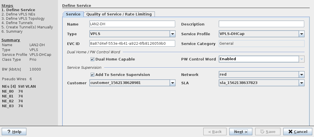
→ Enter a service name.
→ Accept the Type: VPLS (this is the default in this dialog).
→ Select a Service Profile.
→ Optional parameters: Description.
→ If required, set a mark in the “Dual Home Capable” checkbox.
→ If required, set a mark in the “Add To Service Supervision” checkbox, and
→ select Network, Customer, and SLA (Service Level Agreement).
Note:
The selection of a Service Profile assures a consistent use of the relevant parameters throughout the MPLS-TP network.
→ Select the “Quality of Service / Rate Limiting” tab.
1 (b) Define Quality of Service / Rate Limiting:
Note:
Some of the parameters may not be selectable when a Service Profile is used.
→ Select the CoS Type.
→ Select the Default Priority (0…7).
→ Select CoS Overwrite.
→ Select Overwrite Priority.
→ Enable Rate Limiting if required.
→ If Rate Limiting is enabled, enter the CIR, CBS, EIR, and EBS values (or leave them on their defaults).
→ Select the Scheduling Profile (1…5). The 5 scheduling profiles are as configured via the FOXCST (NE – QoS – TC Scheduling Profiles – Profile 1…5). Profile 1 is always a strict priority profile.
→ Click “Next” button.
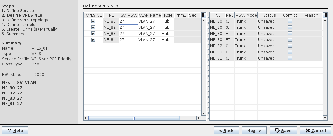
2 Define VPLS NEs
→ Mark the member NEs of the VPLS instance.
e.g NE_172.31.68.80 (NE80), NE_172.31.68.82 (NE82), NE_172.31.68.83 (NE83)
→ Enter a SVI VLAN Id for each node.
Note:
− If the VLAN Id specified by user does not exist on the node, the ENP automatically creates this VLAN.
− The provisioned bridge ports and VLANs for each node are displayed in the ENP GUI > NE Tab > “NE details”. If no ports have been provisioned for the SVI VLAN no ports are listed.
Note:
The prerequisite for provisioned ports is the assignment of VLANs to CVP ports via the FOXCST GUI. For that purpose open the FOXCST GUI (as manager) for the required node(s), select the “Switching” tab, then “Switching – Bridges – bridge-1”, and assign a VLAN ID or a PVID to the required port(s), depending on the selected port mode. Apply the changes to the NE.
Also see Preconfiguration Process via FOXCST.
− The “Role” for each node is set to “Hub”.
This means, the node will be connected to all VPLS nodes, e.g. NE_172.31.68.80 (NE80) will be connected to NE82 and NE83 by Pseudo Wire 1 and 2. NE82 and NE83 will be connected by Pseudo Wire 3. No traffic is forwarded between two Pseudo Wires.
If you only have NEs with Mesh Binding do not select nor define any VPWS ports in the following two step 3.
− If you need to add spoke NEs select “Spoke” in the “Role” column for the respective NE.
In this case you will need to select and define VPWS ports for the Spoke NE(s) in the following two step 3.
− As an option the Role for a specific NE can be set to “PE Dual Home” if this is the required architecture for the NE. In this case the role of the NE in the network is not represented by a fully meshed PW binding, but by a dual home based PW binding for the respective services.
When the Role is set to “PE Dual Home”, select the Primary Node and Secondary Node to the PE Dual Home NE for this specific service. Also select the Protection Mode, either “Revertive” or “Nonrevertive”.
Note:
The use of the “PE Dual Home” role requires NE software that supports the PE Dual Home feature.
→ Click “Next” button.
3 Define VPLS Topology (optional).
Here you can make further changes to the topology of the service’s view of the network.
(a) Tab “VPLS Topology”:
− These two lists show the topology of NEs for the current service.
(b) Tab “VPWS Ports”:
− You can add VPWS ports to the service. Select an NE from the list of NEs, then select the required ports that are available on the NE. Each added port needs to be confirmed.
− Only ports of the type “PWAC” or “CVP” can be selected. The port Type is given by the configuration done via the FOXCST GUI.
→ Select VPWS ports to be added to the service; for each port select the following (options available for selection are depending on the Port Type):
− VPWS Type:
- AC Port Based, No Change,
- AC Port Based, Add PW Tag,
- AC VLAN Based, No Change,
- AC VLAN Based, Change Tag (enter a AC VLAN ID and a PW VLAN ID as required),
- AC VLAN Based, Add PW Tag,
- AC Untagged, No Change,
- AC Untagged, Add PW Tag.
− AC VLAN (where applicable),
− PW VLAN (where applicable).
− Attached to NE: select the NE to which the port is attached.
− Status (read-only),
− Reason (read-only).
“Show all ports” also shows ports that are not suitable for being added. This is for information purposes only.
(c) Tab “Pseudo Wire”:
The Pseudo Wires between each VPLS NEs are automatically created with default values.
→ Use the default values for the following parameters (or change where required):
− Pseudo Wire Name,
− Description,
− Min Label / Max Label,
→ Enter or modify the bandwidth for each of the Pseudo Wires in the “BW [kbit/s]” column / field.
(d) Tab “Port Rate Limiter”
Rate limiter settings can be done here, provided that the ingress rate limiting parameters of the service profile used for this service have been set to “Variable”.
− From the list of ports, select any of the ports that are part of the service.
− On the right-hand side of the dialog, enter the required port specific rate limiting values (CIR, CBS, EIR, EBS).
− If rate limiting shall not be applied to the selected port, disable port rate limiting by removing the mark in the “Enable Rate Limiting” checkbox.
− Do these steps for all ports as required, or leave the settings as defaulted by the service profile.
→ Click “Next” button.
4 Define Tunnels
Lists the tunnels required for implementing the service. Where suitable tunnels already exist, these are used. Where no suitable tunnel exists, a new tunnel needs to be created. You can select to create the tunnel(s) manually or automatically.
→ Select a tunnel.
Accept the automatically proposed tunnel, or click on the tunnel name (in the “Tunnel” column) to choose a different tunnel.
→ If you prefer more options, click on “Tunnel Details”, which allows you to:
− Enable/disable protection,
− Enable/disable forcing distinct path,
− Use advanced routing,
− Enable encryption by selecting an encryption profile,
− Modify minimum and maximum tunnel label.
→ Close the tunnel details dialog window.
→ If required, modify the PW bandwidth by entering a different value. The “Tunnel Action” and “Error” fields are updated accordingly to show details about the modifications.
Note:
If any of the existing tunnels or “create automatically” option is selected, the Wizard will proceed directly to the final step “Summary”. If “create manually” is selected the tunnel(s) need to be selected in the next step.
→ Depending on the tunnel routing status, click the “Automatic Routing” or “Next” button.
− If manual routing is required, the window contents changes to the tunnel details view where you can execute the routing.
5 Create Tunnels Manually
Where required, route the tunnels manually. For this purpose, select the appropriate tunnel end points.
− When done, click “Next” to get back to the “Define Tunnels” (step 4) view.
→ Click “Next” button
6 Summary
Shows a summary of the settings done in the previous steps.
→ If you need to make modifications, go back to previous step.
→ If the service definition is as required, click “Save” to save the service to the database.
→ To deploy the service to the network, select the saved service in the list of VPLS services, then select “Deploy VPLS” from the icon list or from the context menu. The following sequence is checked:
− checks that the path is still valid,
− adds configuration to devices,
− validates that the configuration is accepted and the tunnel is up.