
Preconfiguration Process via FOXCST
The FOXCST configuration steps described in this section assign:
• The MPLS-TP port types:
− MPLS-TP,
− PWAC (for VPWS only),
− CVP (for VPLS only).
• The Switching configuration for VPLS service
− Port Mode: Access, or General,
− VLAN IDs (optional), or PVID, depending on your requirement.
Note:
It is also possible to create VLANs via ENP during service creation.
− VLAN membership.
Please note:
For details refer to the following document:
• MPLS-TP user manual [1KHW028618].
FOXCST preconfiguration for VPWS
FOXCST preconfiguration for VPWS and VPLS
1 Launch the FOXCST of the selected MPLS-TP node:
NEM Desktop > Application > NEM Configurator > NE Browser > Agents > Agent with your MPLS NEs > right click on the required NE,e.g. NE80 > Configuration > Manager
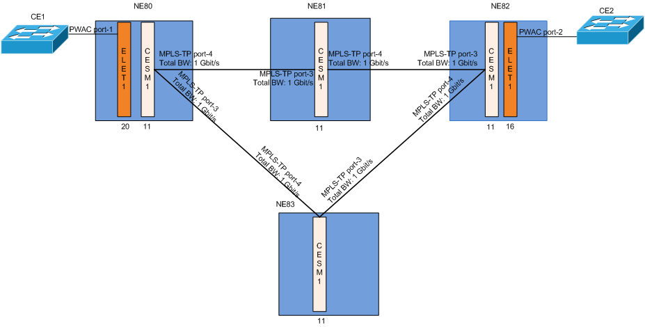
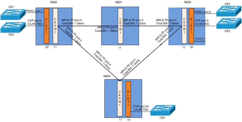
2 Configure NEs Global ID and Node ID:
FOXCST > MPLS-TP Tab > Select “MPLS-TP” in the tree
A possible combination of these IDs are listed below:
NE | Global ID | Node ID |
|---|---|---|
NE80 | 1 | 80 |
NE81 | 1 | 81 |
NE82 | 1 | 82 |
NE83 | 1 | 83 |
− The pair of Global ID and Node ID must be unique
− Add all Known Network Elements with their Global ID, Node ID and Description.
− Export the Known Network Elements to a file via the “Export…” button.
− An all other nodes you can import this file via the “Import…” button so that all NEs have the same set of Known Network Elements.
3 Configure the CE and MPLS-TP network facing interfaces:
• Select the “Tree View” of the FOXCST. Navigate to the port type configuration dialog of the Ethernet user port:
AP:ne/unit-<x>/port-<x>, Main - Port Type - Set Port Usage
The Port Usage allows flexible configuration of any Ethernet interface in the FOX61x chassis to support specific functions as listed below:
− MPLS-TP
These are Ethernet ports on CESM1. These ports can be used for LSP or node label switching: ingress, switch or egress ports (NNI)
− PWAC (Pseudo Wire Attachment Circuit)
These are Ethernet ports on the control unit or Ethernet service units. These ports can be used as A End or Z End of attachment circuits (UNI) for VPWS
− CVP (Customer VLAN Port)
These can be Ethernet ports on Control unit and Ethernet service units
Any port that is configured as CVP connects to the VLAN bridge. These ports can be used as “A End” or “Z End” of attachment circuits for VPLS.
− VLAN Subinterfaces
Any port that is configured as “VLAN Subinterfaces” port, having at least one VLAN and a bandwidth assigned, can be configured as MPLS-TP port. Such MPLS-TP ports are used to transport MPLS-TP traffic through a layer 2 network, using specific VLAN ID(s).
The “None” and “Analyzer” functions are not relevant here.
• Set up bridge VLANs, e.g. VLAN 700 (for VPLS only, optional since VLANs can also be created during service creation in ENP):
− Select “Switching” view of the FOXCST. Navigate to the ports configuration dialog:
AP:/Switching/Bridges/bridge-1 - Ports
− Configure the /unit-<x>/port-<x>:
e.g. ELET1-20/port-2,
Mode= Access,
PVID=700,
Default Priority=0.
• Configure the MPLS-TP related port types on CESM1 unit
− Select the “MPLS-TP” view of the FOXCST. Navigate to the configuration dialog of the MPLS-TP interfaces:
AP:/MPLS-TP/MPLS Interfaces, Interfaces
− Click the  button to open the “Select Port” dialog.
button to open the “Select Port” dialog.− Select the CESM1 front port connecting to the packet switched network to be an “MPLS-TP” port, e.g. /unit-11/port-4.
− Repeat the steps for unit-11/port-3.
− Execute “OK”.
4 Set the administrative state of all involved managed objects to up:
Please note:
The total MPLS-TP port bandwidth is computed from the physical port characteristics of the MPLS-TP interfaces, e.g. CESM1 port-1 is 1 Gbit/s.
5 Save the FOXCST configurations to the nodes.
Please note:
The ENP does not have to wait for the FOXCST configuration “Save” to synchronize its ENP tables.
6 Repeat steps 1 to 4 with NE82, NE81 and NE83. Refer to Network Requirements table for the required parameters.