Create a Tunnel
Tunnel without Protection
The VPWS and VPLS can share the transport tunnel(s). We will see later that Tunnel A will be used as transport by both the VPWS and VPLS, whereas Tunnels B and C will be used only by VPLS in the example shown here.
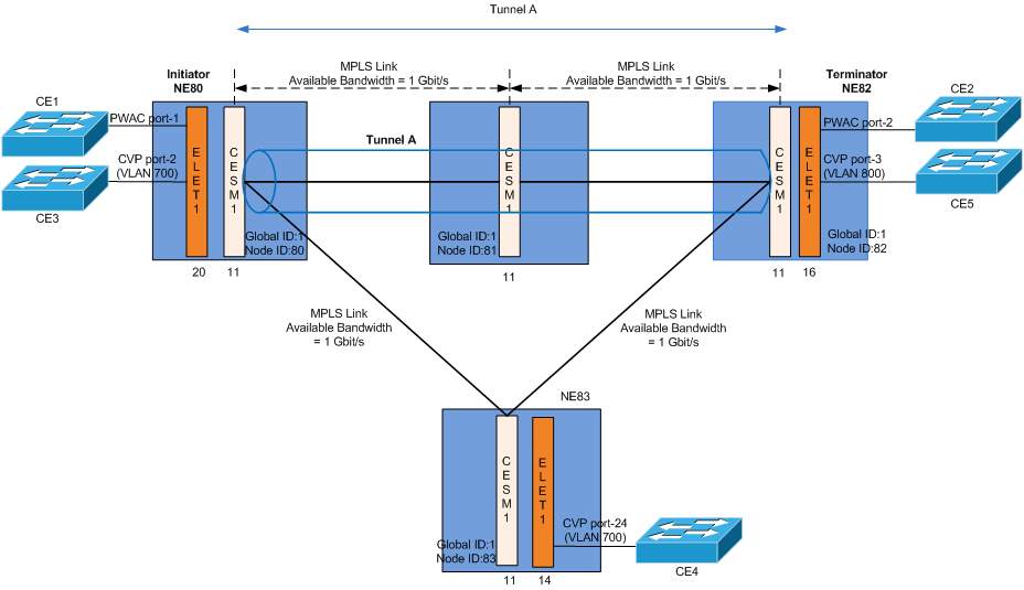
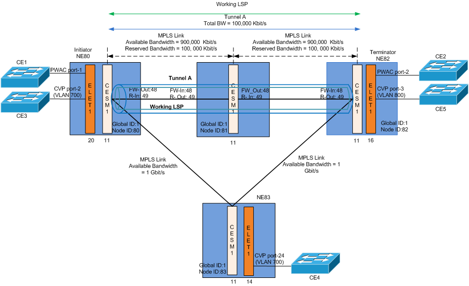
Tunnel A
1 Launch the Create Tunnel dialog:
ENP > Tunnel Tab > Edit > Create Tunnel
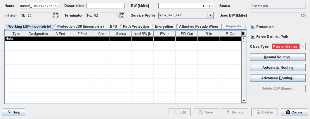
2 Select the node endpoints, i.e. NE80 as Initiator and NE82 as Terminator. Enter the allocated tunnel bandwidth. This creates a tunnel connecting the two endpoints.
3 Create the Working LSP or Working Path
When a tunnel is being created, the route has not been defined thus the Path contains a “Hole”. The user can select Automatic (recommended), Manual Routing or Advanced Routing to complete the route.
→ Click on “Working LSP” tab.
→ Select the “Hole” and Click on “Automatic Routing” button.
The ENP creates Working LSP automatically based on the cheapest routing order. This means the routing engine takes into account the configured link’s cost. The calculated path has the lowest overall link cost in the network.
Please note:
Regardless of the routing selected, the link will not be taken into consideration in the path selection if its available bandwidth is not enough to accommodate the tunnel bandwidth requirement.
The path can be modified by removing the LSP elements. Select the LSP elements that you want to remove and then click on “Delete LSP Element” button and invoke again the Automatic (or Manual) routing on the missing section.
4 Validate the path by clicking “Save” button. The ENP system then:
− assigns the LSP labels (FW-Out/FW-In, R-In/R-Out),
− updates the Used and Reserved link bandwidth.
5 For VPWS only, proceed back to step 4 of Create a Virtual Private Wire Service (VPWS).
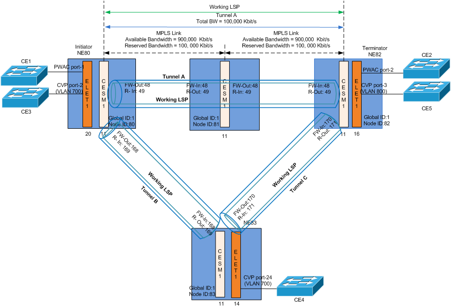
Full Mesh Tunnels
To create an emulated LAN based on VPLS architecture, a full mesh consisting of Pseudo Wires is set up to connect all VPLS instances of member edge routers. Therefore full mesh tunnels (LSPs) between all these nodes should be created.
For H-VPLS spoke NEs are also admitted; however each spoke NE needs to be attached to a mesh NE.
To simplify the discussion, we shall configure unprotected Tunnels only.
Tunnel A, Tunnel B, Tunnel C (without Protection)
In this use case, NE80, NE82 and NE83 are all member edge routers of the VPLS instance. (Note NE81 is not VPLS member). The tunnels without protection as listed in the table below, will serve as transport to carry the full mesh VPLS Pseudo Wires over the MPLS-TP provider network.
1 Tunnel A can likewise be used to carry the VPLS Pseudo Wire as long as there is enough bandwidth to carry the additional load.
2 Tunnels B and C can be created by repeating steps 1 to 4 described in creation of Tunnel A. Change the Initiator and Terminator NEs for each tunnel as listed in the table below:
Tunnel | Initiator | Terminator | Carried Service(s) |
|---|---|---|---|
Tunnel A | NE80 | NE82 | VPWS, VPLS |
Tunnel B | NE80 | NE83 | VPLS |
Tunnel C | NE82 | NE83 | VPLS |
3 Proceed back to step 4 of Create a Virtual Private LAN Service (VPLS)
Tunnel with Protection
For background information about OAM and Protection switching, please refer to Introduction sections OAM and BFD and Protection Mechanism.
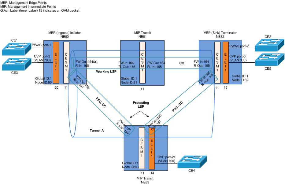
Tunnel A with Protection
1 Launch the Create Tunnel dialog:
ENP > Tunnel Tab > Edit > Create Tunnel
2 Click the “Protected” Checkbox.
− This activates the Protection LSP tab, Path Protection tab and BFD sessions for the working and protection LSP.
3 Select the node endpoints, i.e. NE80 as Initiator and NE82 as Terminator. Enter the allocated tunnel bandwidth. This creates a tunnel connecting the two endpoints.
4 Select the “BFD” tab and select the Continuity Check (CC) Interval for the Working and Protection LSPs.
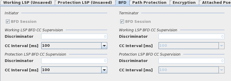
The local MEP sends CC OAM packets periodically every CC interval. The remote MEP monitors the arrival of these packets and detects loss of continuity (LOC) if no CC packet is received within the period of 3 x CC Interval. The user data is then switched to the protection LSP.
In case of revertive switching, a short CC interval is only required on the Working LSP. To achieve sub-50 ms path protection switch over time, a 3.3 ms CC interval is recommended. A longer CC Interval can be selected for the protection LSP since the switch-over from the protection LSP to working LSP is controlled by the Wait-to-Restore (WTR) timer.
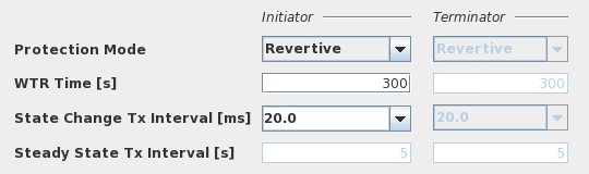
5 Select the “Path Protection” tab and define the Path Protection parameters:
Parameter | Description |
|---|---|
Protection Mode: Revertive | When the signal fail condition is no longer active and after the expiry of the wait-to-restore (WTR) timer, the user traffic is switched back from the protection LSP to the working LSP. |
Protection Mode: NonRevertive | The user traffic remains on the protection LSP even if the signal fail condition is no longer active. |
WTR Time [s] | Wait-To-Restore time for the revertive protection mode. The user traffic is switched from protection to working LSP only after the expiration of the wait-to-restore timer. Accepts values from 0 to 720 ms |
State Change Tx Interval [ms] | The time interval to send three protection state coordination (PSC) protocol packets when there is a state change, e.g. a defect. Accepts values 3.3, 10 and 20 ms. |
Steady State Tx Interval [s] | The time interval to send the protection state coordination (PSC) protocol packets when there is no state change. |
Protection Status, Command | Not relevant during tunnel creation, but only for deployed tunnels. For details refer to Path Protection. |
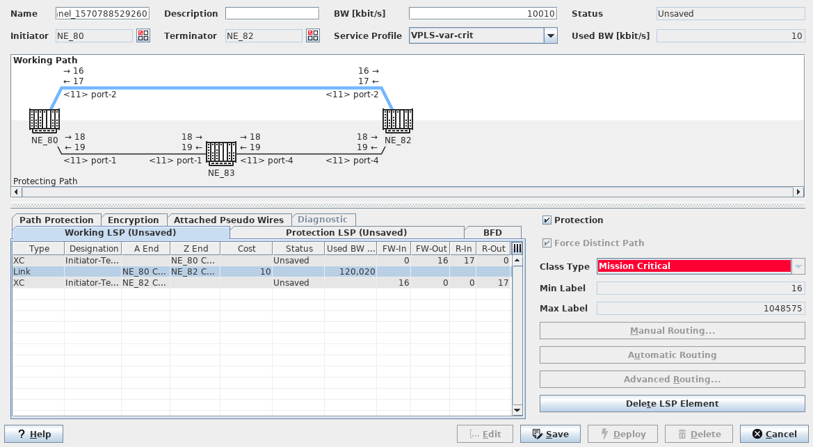
6 Select the “Working LSP” tab.
The user can select Automatic (recommended), Manual Routing or Advanced Routing to complete the route.
− Select the “Hole” and click on “Automatic Routing” button.
The ENP creates Working LSP automatically based on the cheapest route.
7 Select the “Protection LSP” tab.
The user can select Automatic (recommended), Manual Routing or Advanced Routing to complete the route.
− Select the “Hole” and click on “Automatic Routing” button.
The ENP creates Protection LSP automatically based on the cheapest route.
8 Click “Save”. Modify the tunnel configurations as required.