
Protection Mechanism
In order to provide fast protection switching times, working and protection LSPs are preconfigured and relevant bandwidth is reserved.
In the 1:1 bidirectional protection switching, a selector at the source of the protection domain selects the path that carries the client or user traffic.
Since both endpoints (MEP A and MEP Z) need to be coordinated to ensure that the selector at both ends select the same path, this architecture supports a protection state coordination (PSC) protocol, which is transmitted on the protecting path.
The figure below details the kind of traffic carried by the working and protecting LSPs during normal state.
Normal State
Under normal state, both working and protection paths are fully allocated and active. The user traffic is sent and received on the working LSP.
.
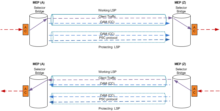
Continuity check packets are sent at a defined “CC Interval” on both the working and protecting LSPs. In order to achieve 50 ms switching during protection, CC packet should be sent every 3.3 or 10 ms.
The PSC protocol packets indicating no state change are transmitted on a regular interval on protecting LSP.
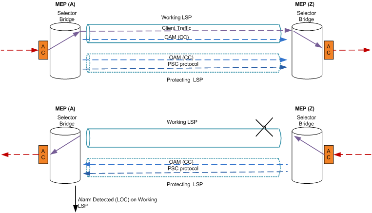
Failure State
The graphics below show a failed condition is detected in the direction from MEP Z to MEP A.
MEP A, detects a Loss of Continuity (LOC) on working LSP because it failed to receive CC packets within 3 times the configured “CC Interval”.
Failure State: Switching at A
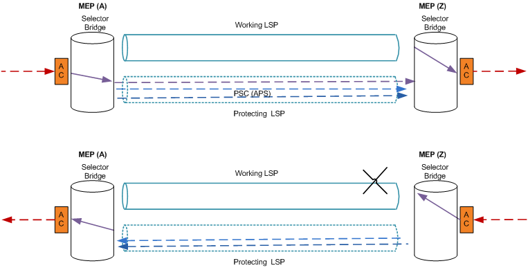
Upon detection of LOC, the PSC initiates protection switching.
The selector bridge at MEP A is switched to protecting LSP to send and receive user traffic.
Please note:
The switching from working to protecting LSP can be triggered by:
• various failure conditions (e.g. link failures) or
• administrator/operator interventions (such as shut-down, lockout of working/forced switch, and lockout of operation.) These manual interventions can only be done via FOXCST.
MEP A also sends three rapid PSC messages to MEP Z indicating signal fail on the working LSP and switching from working to protecting LSP. This set of three rapid PSC messages must be transmitted as quickly as possible, e.g. 3 ms, to allow for fast protection switching.
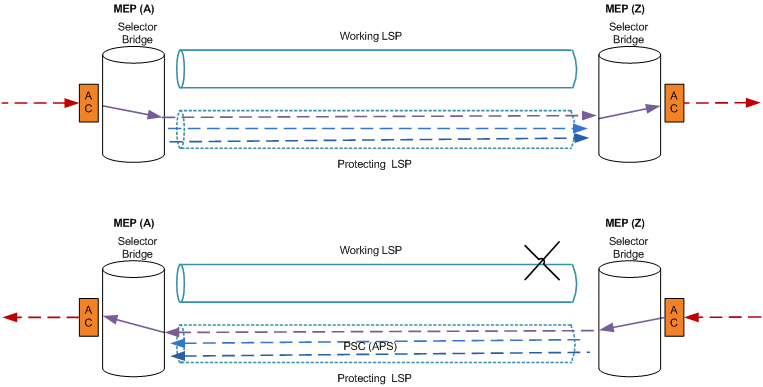
Failure State: Switching at Z
After MEP Z validates the PSC messages from MEP A, the selector at MEP Z switches to protecting LSP. It then sends an acknowledgment PSC packet to MEP A, informing it about the switching.
Wait-to-Restore and Do-not-Revert State
Under Wait-to-Restore (WTR) state, the protection domain is recovering from a signal fail or signal degradation condition on the working path that is being controlled by Wait-to-Restore timer. Under the revertive mode, the user traffic is automatically switched from the protection path to the working path after the expiration of the Wait-to-Restore (WTR) time.
Under Do-not-Revert state, the protection domain has recovered from a protecting state (no signal fail), but the operator has configured the protection domain as non-revertive mode. Under this mode the protection domain does not automatically revert to normal state upon recovery. The protection domain shall remain in this state until the operator issues a command to revert to the normal state or there is a new trigger to switch to a different state.