
Create VPWS
The “Create VPWS” wizard is started with the “+ Create” button from the ribbon of the VPWS tab in the MPLS-TP Map.
The “Modify VPWS” wizard is started for a selected VPWS with the “Modify VPWS” command from the action menu of the selected VPWS.
Please note:
A VPWS can be modified using the command “Modify VPWS”. This command will open the “Modify VPWS: <VPWS Name>” wizard, which provides the same steps as the “Create VPWS” wizard, but with some restrictions regarding modification of settings, i.e., not all parameters can be modified.
The wizard leads you through 6 basic steps of creating a new VPWS in your MPLS-TP network.
The steps below show the creation of a sample VPWS,
Step 1: General
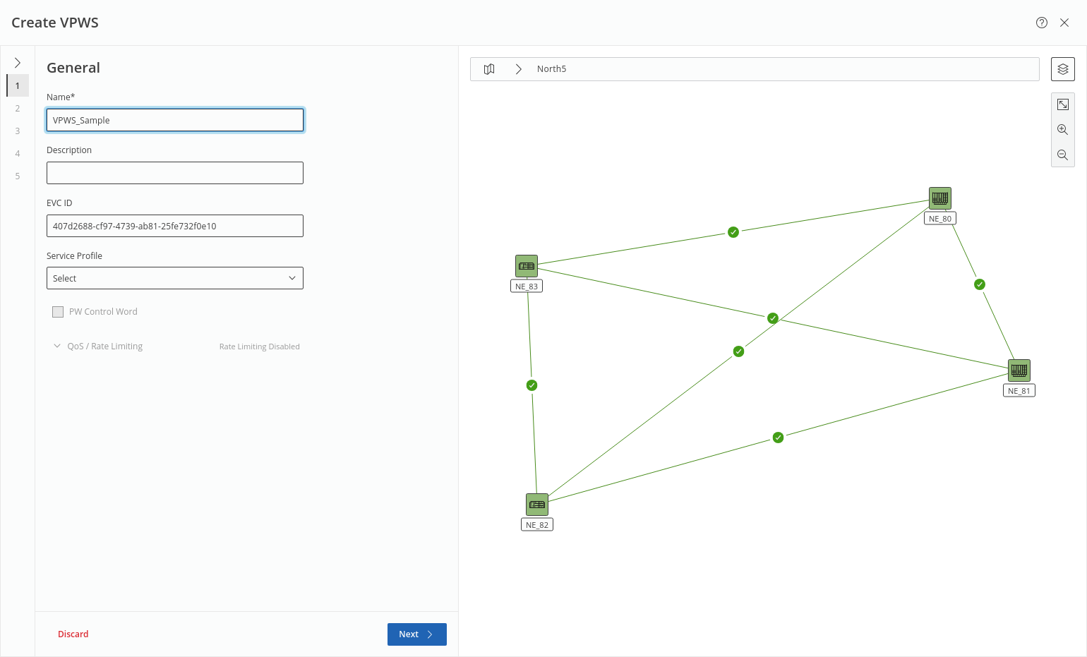
This step requires at least a unique name for the new VPWS and an appropriate service profile before proceeding to the next step.
The service profile is used to define the “PW Control Word” and “QoS / Rate Limiting” settings. The description is optional; the EVC ID is generated automatically.
If the selected service profile permits, PW Control Word can be enabled or disabled, and QoS / rate limiting properties can be configured after expanding the “QoS / Rate Limiting” field.
The map on the right hand side shows the progress through all steps.
Click “Next >” to proceed to step 2.
Step 2: Attachment Circuit
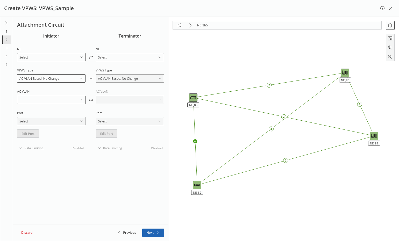
This step defines the AC properties on the Initiator and Terminator ends of the service. For each end, you need to select
• NE,
• VPWS Type,
• AC VLAN (optional, also depends on VPWS type),
• PW VLAN (optional, depends on VPWS type),
• Port.
A port can be edited to make it better suitable for the service if required by clicking on the “Edit Port” button. This will allow you to set “Label 1”, “Label 2”, “Description”, “Port Type”, and “Admin State” of the port. Such a change needs to be deployed before continuing.
If the selected service profile permits and rate limiting is enabled, rate limiting properties can be configured after setting the above properties and after expanding the “Rate Limiting” field. Rate limiting can also be disabled here if the service profile permits.
Click “Next >” to proceed to step 3.
Step 3: Pseudo Wire
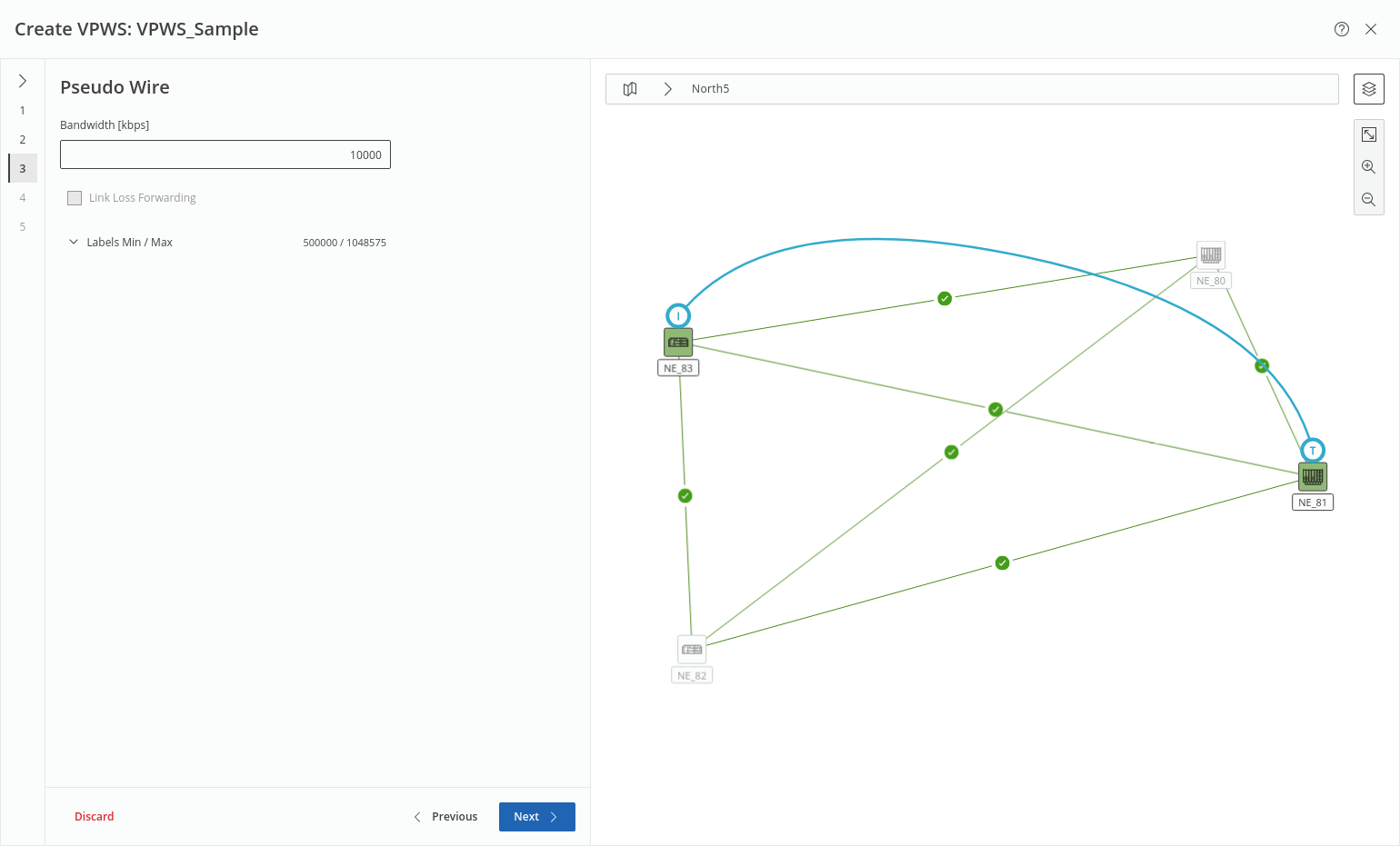
This step has no mandatory fields. Depending on the selected service profile it may allows you to modify the bandwidth and the “Min Label” and “Max Label” values. Link Loss Forwarding (LLF) can be enabled or disabled if the involved units support the feature.
Click “Next >” to proceed to step 4.
Step 4: Tunnel
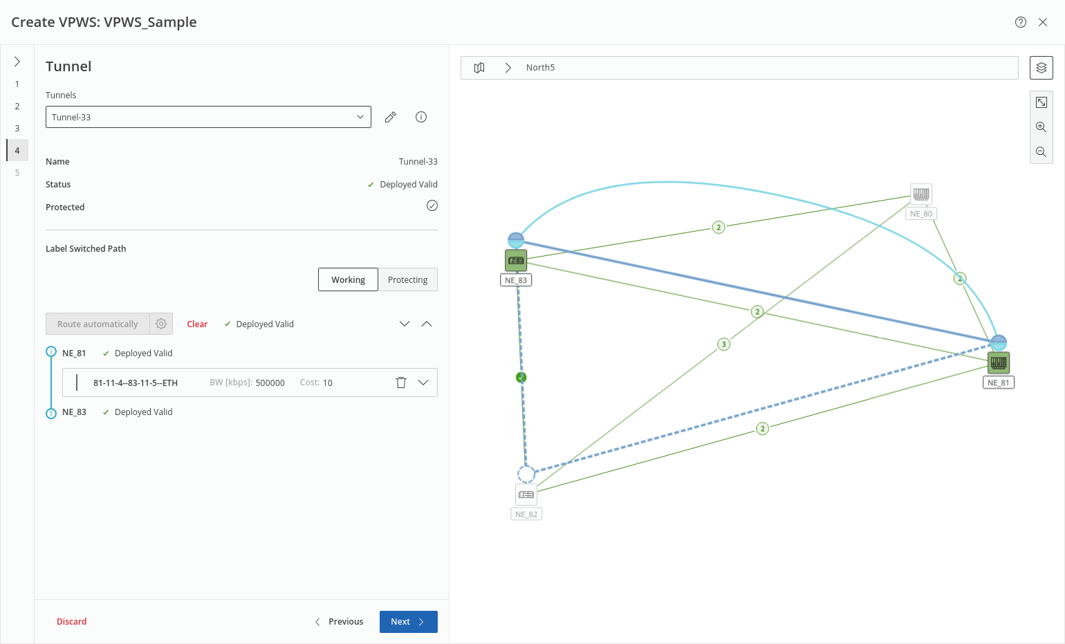
This step proposes a tunnel to be assigned for the service. If no suitable tunnels exist, the proposed tunnel can be modified, or a new tunnel can be created.
To modify a tunnel, click on the pen icon right to the tunnel selection field. This will open a new modal window where you can edit tunnel parameters (editability depends on the selected VPWS service profile) such as
• Name,
• Description,
• Class Type,
• Bandwidth,
• Protected (true, false),
• Force Distinct Path (true, false),
• Service Profile,
• BFD Session (true, false),
• Working CC Interval / Protection CC Interval,
• Revertive Mode,
• WTR Time,
• State Change Tx Interval.
To apply the tunnel modifications, click “Apply”.
Under “Label Switched Path”, the button “Route automatically” executes an automatic routing individually for the working and the protecting LSPs, respectively. Auto Routing Parameters can be set via the gear icon of the command button. While routing, status of working and protecting LSPs and missing elements are indicated in-line. After routing, the new tunnel name is listed with its auto-assigned name.
The proposed tunnel (working and protecting LSPs) is shown on the map. For protected tunnels, make sure both working and protecting tunnels are routed by selecting the respective field “Working” or “Protecting” and applying required settings.
More information on the tunnel and additional settings, such as
• Protection options (working and protecting LSPs),
• Deployment status,
• Initiator and terminator NEs,
• Selected section / link,
is obtained by expanding/collapsing the Label Switched Path field via the down/up arrows  . The expanded LSP fields provide all tools to finally select an appropriate tunnel for the new service.
Once the tunnel shows a green OK mark in the Status field the step is completed.
Click “Next >” to proceed to step 5.
Step 5: Summary
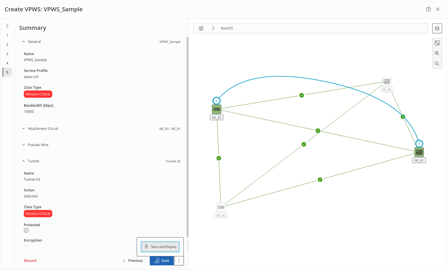
This step shows a summary of the relevant settings related to General, Attachment Circuit, Pseudo Wire, and Tunnel (LSP) properties. The respective fields can be expanded/collapsed via the down/up arrows .
Once the service settings are verified, either
• click the “Save” button to execute a save action for the service and its components or
• click the three-dots menu button right to it and execute “Save and Deploy” to save and deploy the new service and its components to the network.
In both cases, the progress and status are shown.
Click “Finish” to close the wizard and return to the MPLS-TP Map view.