
Create Tunnel
The “Create Tunnel” wizard is started with the “+ Create” button from the ribbon of the Tunnel tab in the MPLS-TP Map.
The “Modify Tunnel” wizard is started for a selected tunnel with the “Modify Tunnel” command from the action menu of the selected tunnel.
Please note:
A tunnel can be modified using the command “Modify Tunnel”. This command will open the “Modify Tunnel: <Tunnel Name>” wizard, which provides the same steps as the “Create Tunnel” wizard, but with some restrictions regarding modification of settings, i.e., not all parameters can be modified.
When you re-route a deployed tunnel while removing two consecutive LSP elements, a special procedure is required, see Modify Tunnel (special procedure).
The wizard leads you through 6 basic steps of creating a new tunnel in your MPLS-TP network.
The steps below show the creation of a sample tunnel,
• Step 3: OAM,
Step 1: General
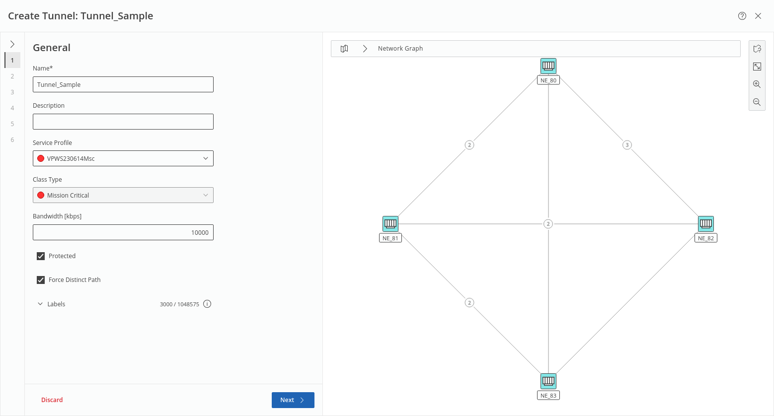
This step requires at least a unique name for the new tunnel, and selection of either an appropriate service profile or Class Type is strongly recommended before proceeding to the next step. Modification of some of the settings won’t be possible once the tunnel is saved.
If a service profile is selected, most of the parameters are given by the service profile.
If no service profile is selected, Min Label and Max Label can be selected manually; default range is 3000 … 1048575.
Click “Next >” to proceed to step 2.
Step 2: Endpoint
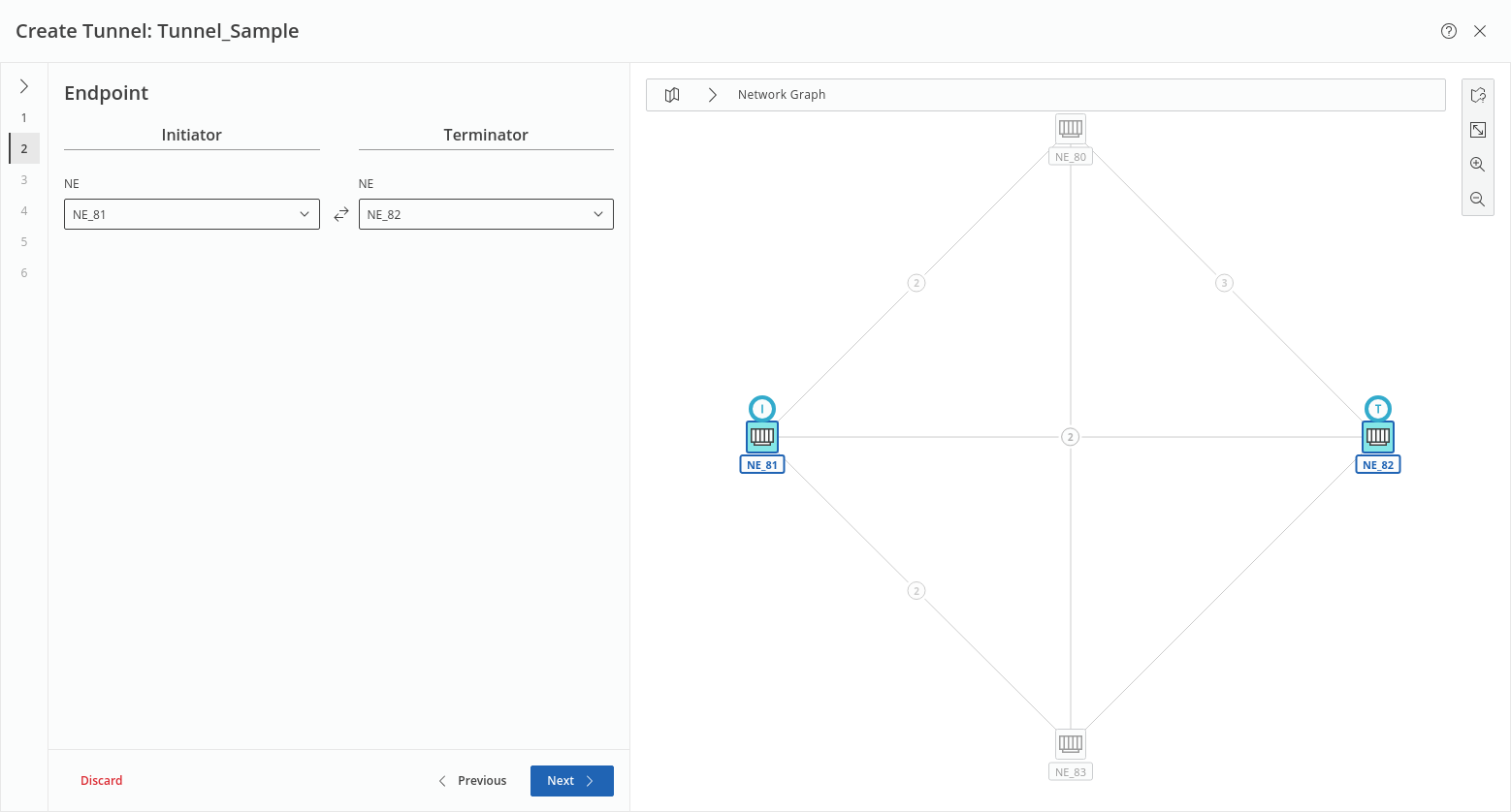
This step requires selection of the two tunnel endpoints (Initiator, Terminator): the NE for each of the endpoints is selected from a list of available NEs.
Click “Next >” to proceed to step 3.
Step 3: OAM
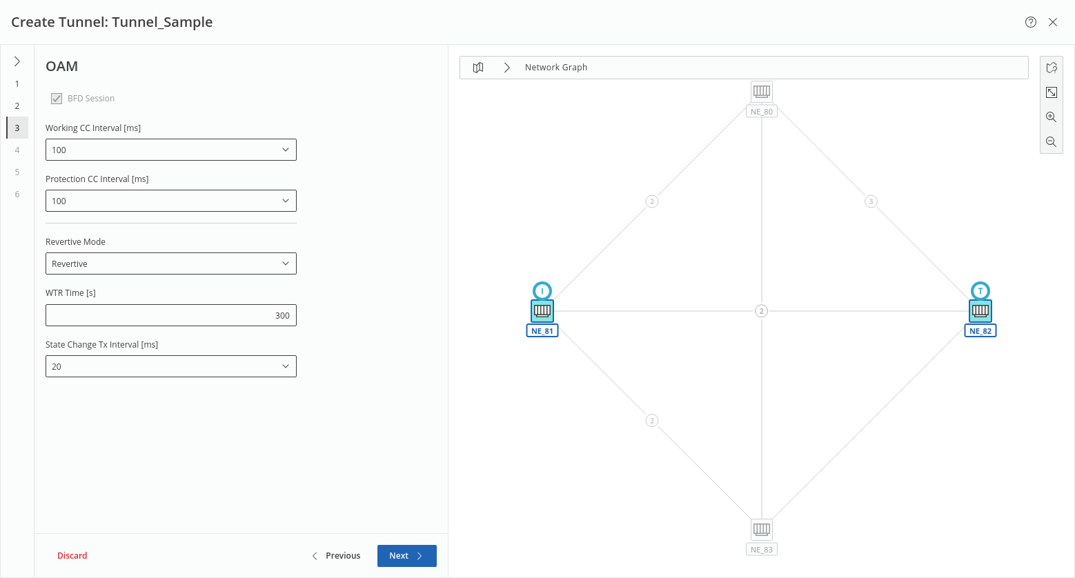
This step lets you defined OAM settings. If you have selected a service profile in step 1, it determines some or all settings.
If no service profile is selected and protection is disabled, you can enable BFD session and set the related parameter Working CC Interval; if protection is enabled, you can additionally set the parameters Protection CC Interval, Revertive Mode, WTR Time, and State Change Tx Interval individually.
Click “Next >” to proceed to step 4.
Step 4: Label Switched Path
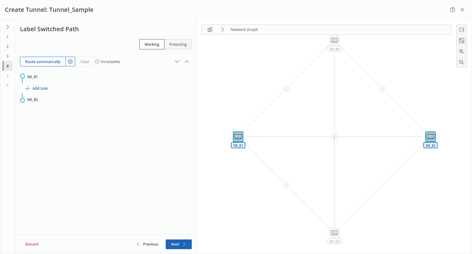
This step shows the tunnel endpoints and lets you route the LSP(s) automatically if the prerequisites are given for automatic routing; usually a valid service profile is the right prerequisite.
Otherwise you may add at least one link (or at least two links for working and protecting LSPs) manually.
The gear wheel icon is used for setting auto routing parameters, such as:
• Routing Order (BW Optimized, Cheapest (default), Shortest),
• Max Hops,
• Max Cost,
• Excluded NEs,
• Included NEs,
• Excluded Links.
The auto routing parameters are applicable separately to working and protecting LSPs.
Once routing is completed, the LSP segments are listed.
Click “Next >” to proceed to step 5.
Step 5: Encryption
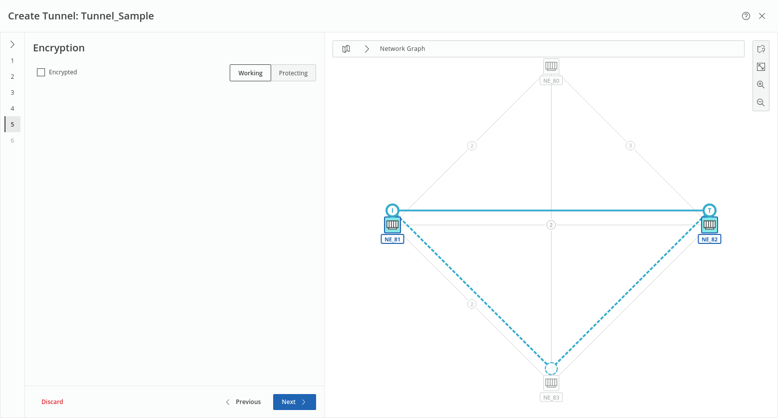
This step lets you enable encryption if you use encryption units and have set up the links accordingly. With protected LSPs, you can enable encryption individually for working and protecting LSPs as far as available on the respective links.
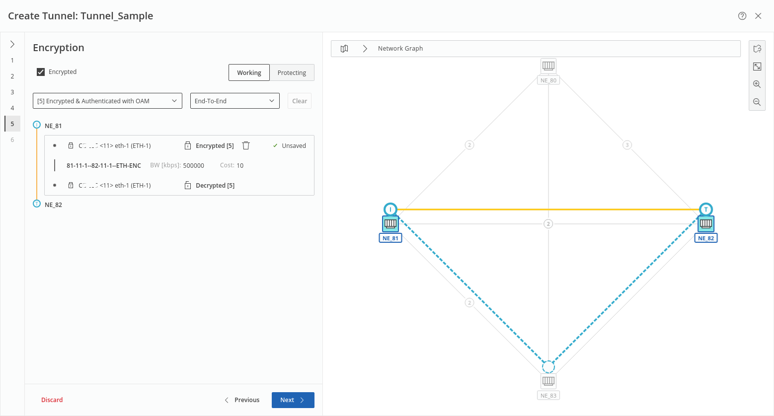
Encrypted links are indicated with a lock symbol in front of the initiating and terminating unit ports. The color of the tunnel between the A and Z end NEs is set to gold. Note that an encrypted tunnel in the MPLS-TP map, “Tunnel” tab, will also be shown colored in gold if the view option to show the context “encryption” is enabled.
Where encryption is supported, e.g., only on working tunnel of a working and protecting pair, it will be saved and deployed to the network accordingly, i.e., when proceeding to the next step, the encryption settings are only taken over where supported by the network.
Click “Next >” to proceed to step 6.
Step 6: Summary
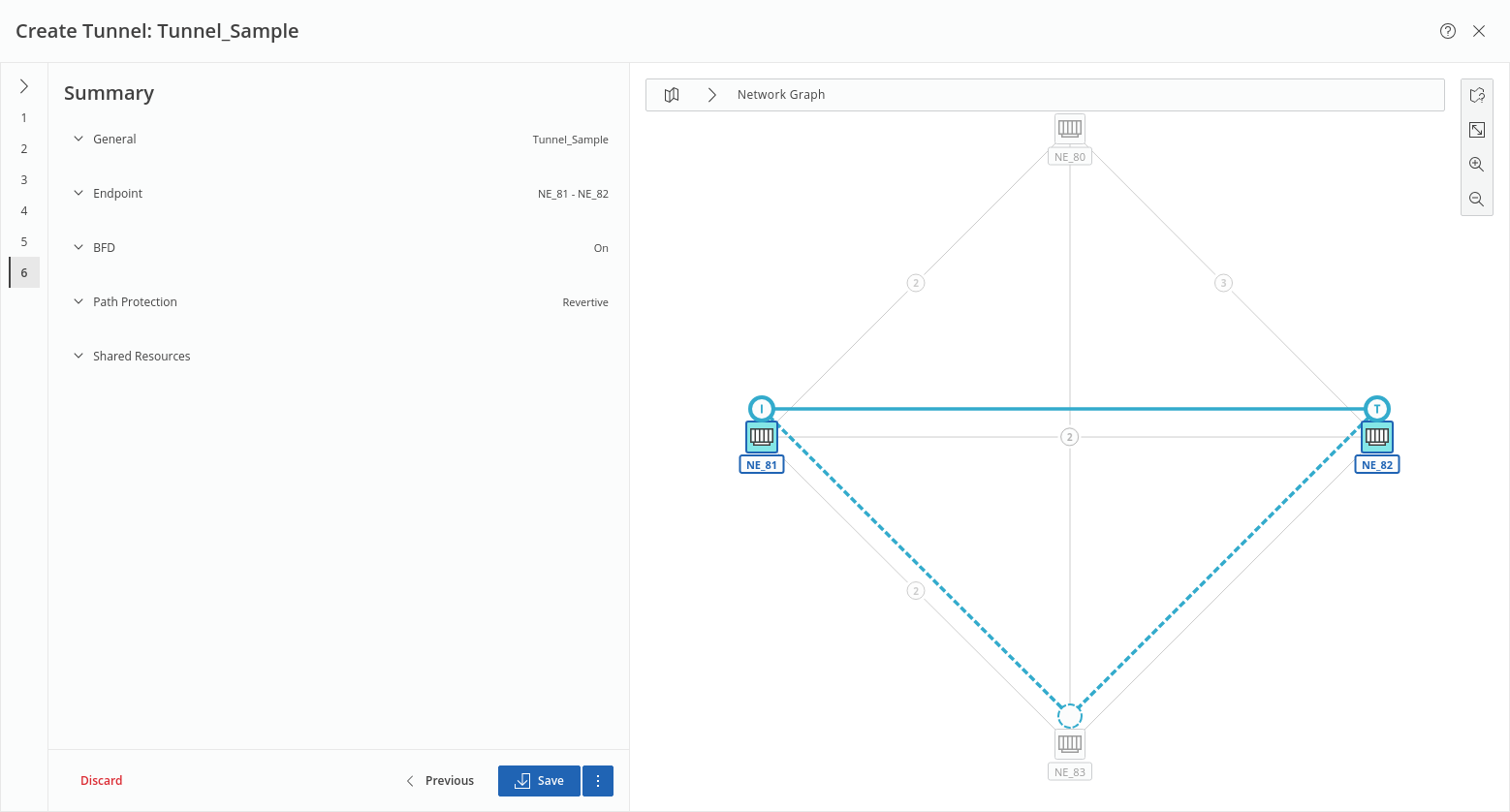
This step shows a summary of the relevant settings related to General, Endpoint, BFD, Path Protection, and Shared Resources.
The respective fields can be expanded/collapsed via the down/up arrows  .
.
Once the tunnel settings are verified, either
• click the “Save” button to execute a save action for the tunnel and its components or
• click the three-dots menu button right to it and execute “Save and Deploy” to save and deploy the new tunnel and its components to the network.
In both cases, progress and status are shown.
Click “Finish” to close the wizard and return to the MPLS-TP Map view.