
Pseudo Wire Details
Purpose
The Pseudo Wire Details dialog (Details tab) displays all the information related to the selected Pseudo Wire including its admin state, the PW member NEs, the ports, Attachment Circuits, and the selected Tunnels in one view.
The PW admin state can be modified in both the “View” and the “Edit” mode.
An “Edit” command button allows you to edit some of the PW parameters:
• Name,
• Description,
• Tunnel (select a different available tunnel for the PW).
An edited PW needs to be saved and deployed to be effective in the network.
Details
The “Details” tab provides the following types of information for the Pseudo Wire as described in detail further below:
• General,
• Attachment Circuits,
• Quality of Service
• Rate Limiting.
Graph
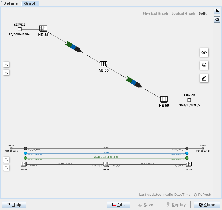
The Pseudo Wire “Graph” tab provides a graphical presentation of the physical and/or the logical view on the PW.
Depending on the dialog window size you can select the physical graph, the logical graph, or a split view with both the physical and the logical graph shown.
The physical graph of the PW shows involved initiator, transit, and terminator NEs (nodes), service access points, and links. It also indicates the different layers (service, Pseudo Wire, tunnel, link) with colors.
The logical graph of the PW shows the logical layers used to provide the service. It uses the same colors for showing the different layers (service, Pseudo Wire, tunnel, link) as the physical graph does.
Working and protecting paths are shown as solid lines and patterns (working tunnel) and dotted line and patterns (protecting tunnel), respectively.
Several view options can be enabled or disabled:
PATHS:
• Working Path,
• Protection Path,
• Sub Protecting Path,
VIEW SETTINGS:
• Show Fixed TEs,
• Show SNCs as Cloud,
• Show Indistinct Sections,
LABELS:
• Show TE labels,
• Show Shared Resource Count,
• Show NE IDs.
A list of possible issues (related to: shared resources; status; holes) can be opened/closed.
The graph can be edited which allows the user to rearrange the NEs (nodes) in the physical graph.
Further options of the graphical view:
• Zoom in / zoom out;
• Open in a separate window;
• Refresh;
• Reset layout - resets the physical graph to the default view.
Dialog image
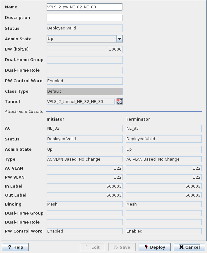
Pseudo Wire (VPLS)
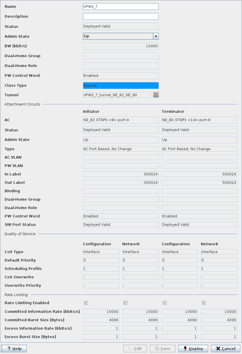
Pseudo Wire (VPWS)
Pseudo Wire Graph
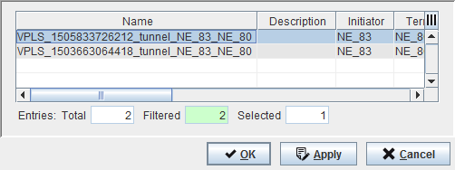
Select Tunnel
Informational content
Name | The specified Name of the Pseudo Wire |
Description | The specified Description of the Pseudo Wire |
Status | The Pseudo Wire status: - Deployed Valid: The Service, and Pseudo Wire are deployed to the MPLS-TP nodes. A deployed Service can be deleted. It can neither be modified nor set back to saved. - Deployed Invalid: One side of the Pseudo Wire is not correctly deployed. It is saved in the FOXMAN‑UN database and is deployed to the nodes. - Saved OK: The Service, Pseudo Wire are saved in the database but not yet deployed in the MPLS-TP nodes. - Saved Incomplete: One side of the Pseudo Wire is not correctly deployed. It is saved in the FOXMAN‑UN database. |
Admin State | The administrative state of the Pseudo Wire. It can be set to “up” or “down”, also via ENP main menu or context menu in the Pseudo Wire tab. |
Operational State | The current PW operational state; when up, the field background is colored green. When down, the field background is colored orange. |
BW [kbit/s] | The allocated Pseudo Wire bandwidth. |
Dual-Home Group | Shows the Dual-Home group name. |
Dual-Home Role | Shows the Dual-Home role. |
PW Control Word | Indicates whether the PseudoWire Control Word is enabled or disabled. |
Class Type | The specified Class Type of the tunnel. |
Tunnel | The specified Name of the tunnel. |
Attachment Circuits (Initiator, Terminator)
AC | The selected NE and port |
Status | The AC status: - Deployed Valid: The item is deployed to the MPLS-TP nodes. - Deployed Invalid: One side of the item is not correctly deployed. It is saved in the FOXMAN‑UN database and is deployed to the nodes. - Saved OK: The item is saved in the database but not yet deployed in the MPLS-TP nodes. - Saved Incomplete: One side of the item is not correctly deployed. It is saved in the FOXMAN‑UN database. |
Admin State | The administrative state of the Pseudo Wire. It can be set to “up” or “down” via ENP menu or context menu. |
Operational State | The current PW operational state at the Initiator and Terminator ends; when up, the field background is colored green. When down, the field background is colored orange. |
Type | The defined AC type. |
AC VLAN | The defined VLAN for the Attachment Circuit. |
PW VLAN | The defined VLAN for the Pseudo Wire. |
In Label | The defined In Label for the AC. |
Out Label | The defined Out Label for the AC. |
Binding | The defined Pseudo Wire binding of the node: Mesh or Spoke. This field is empty when undefined, e.g. if the PW status is “Invalid”. |
Dual-Home Group | Shows the Dual-Home group name. |
Dual-Home Role | Shows the Dual-Home role. |
PW Control Word | Indicates whether the PseudoWire Control Word is enabled or disabled. |
SNI Port Status | Shows the Service-Network Interface (SNI) port deployment status. |
Quality of Service (only if configured for the PW)
Initiator (Configuration, Network)/Terminator (Configuration, Network)
Initiator (Configuration, Network)/Terminator (Configuration, Network)
CoS Type | The Class of Service Type configured on Initiator/Terminator side. |
Default Priority | The Default Priority configured on Initiator/Terminator side. |
Scheduling Profile | The Scheduling Profile applied on Initiator/Terminator side. |
CoS Overwrite | The CoS overwrite mode: - Overwrite, - Maintain, as defined during service creation. |
Overwrite Priority | The overwrite priority for the service as defined during service creation. |
Rate Limiting (only if configured for the PW)
Initiator (Configuration, Network)/Terminator (Configuration, Network)
Initiator (Configuration, Network)/Terminator (Configuration, Network)
Rate Limiting Enabled | Indicates whether Rate Limiting is enabled or disabled for this PW. |
Committed Information Rate [kbit/s] | Shows the CIR in kbit/s for this PW. |
Committed Burst Size [Bytes] | Shows the CBS in bytes for this PW. |
Excess Information Rate [kbit/s] | Shows the EIR in kbit/s for this PW. |
Excess Burst Size [Bytes] | Shows the EBS in bytes for this PW. |
Mandatory entries
Not applicable.
Controls (buttons, menu items, etc.)
? Help | Calls the help viewer and opens this page. |
Edit | Changes the dialog to Edit mode. In the Edit mode the tunnel associated with the PW can be selected. To select a different tunnel, open the “Select Tunnel” dialog by clicking on the  icon. icon.In the Edit mode the “Deploy” button is active. |
Save | Save changes (only available when in Edit mode). |
Deploy | Deploys the changes made to the PW. Only applicable when the Pseudo Wire has been modified, i.e. when in Edit mode. |
Close | Closes the dialog (only available when in View mode). |
Cancel | Closes the dialog without applying changes (only when in Edit mode). |
Related dialogs / windows