
TE Graph
Any selected TE provides a graphical view of the logical and the physical TE diagram. You can zoom in and out with the mouse wheel, via zoom icons or via double-click, switch the view (logical, physical), enable/disable several view options, and edit the NE placement in the physical view.
Via an information icon (i) additional information on possible issues for the TE is provided, such as shared resources, status issues, holes, and alarms.
The logical view shows all logical layers that are relevant for the TE, see TE Graph, Logical View, without banner (sample).
Any transport element of the graph can be highlighted by clicking on it.
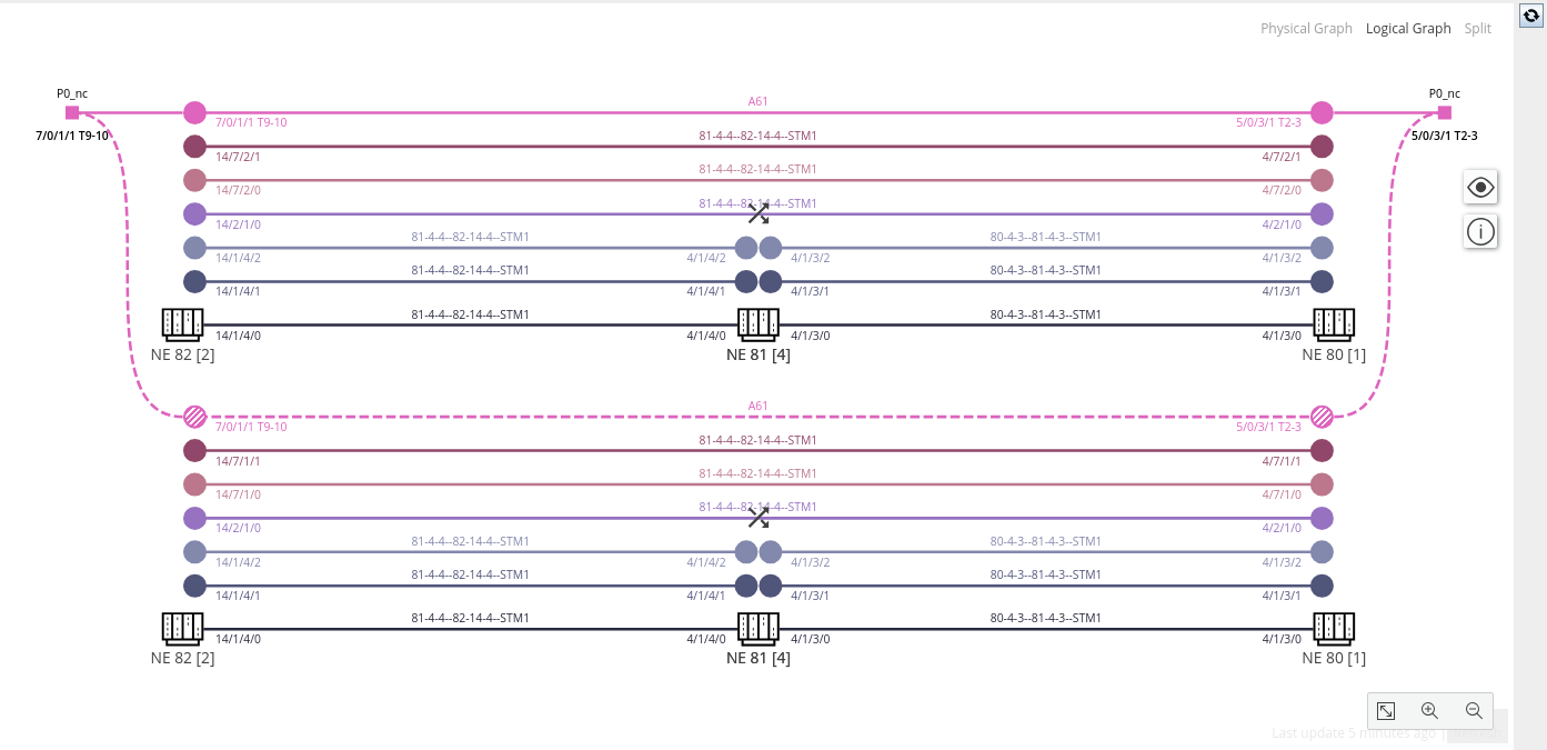
TE Graph, Logical View, without banner (sample)
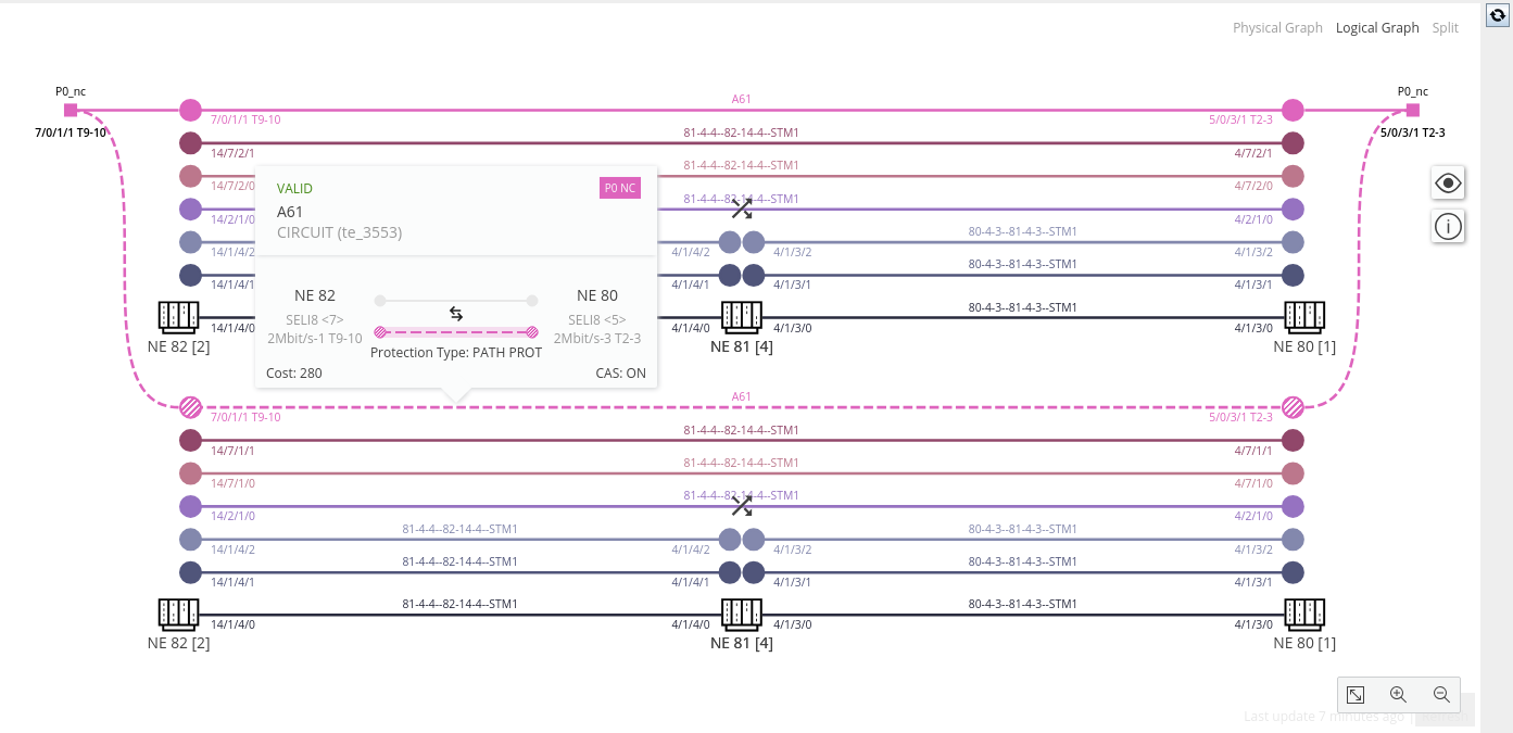
TE Graph, Logical View, with banner for the protected path (sample)
The physical view shows all physical elements that are relevant for the TE, including A-End and Z-End NEs, and Intermediate NEs.
The layer colors shown on the sections correspond to the colors used for the elements in the logical view. The legend of colors used for the different layer rates and sections is listed in the view options.
You can rearrange the NEs in the physical view using the editing mode. The NE arrangement will be stored in the NEM database.
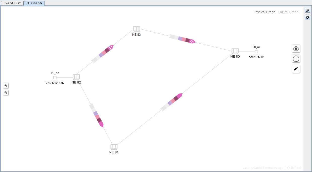
TE Graph, Physical View