
Selected Transport Entity view
This part of the Application focuses on the construct of the TE.
Working Path
In the example, the Application is using a P0_nc Circuit as TE is reflected as a construction built on a
− MC Matrix Connection on NE 82 between LEDE1 and SAMO1.
− LC Link Connection between NE 82 and NE 80 on a P12 layer.
− MC Matrix Connection on NE80 between LEDE1 and SAMO2.
Selected Transport Entity: Working Path
Manual Routing | Calls the Manual Routing: Next Hop List dialog to search for all possible hops having enough capacity for the service to be routed. The user can select one of these hops. NP search then for all possible hops from the selected hop. |
Manual Routing (Hops Calculation) | Calls the Manual Routing: Next Hop List dialog to search for all possible hops having enough capacity for the service to be routed with the additional indication of minimum number of hops to reach the final. The user can select one of these hops. The NP search then for all possible hops from the selected hop. |
Automatic Routing | Enables the route completion in one operation based on the values specified in the Set Automatic Routing Parameters dialog. |
Advanced Routing | Select parameters before executing the routing process. The parameters are the same as in the Automatic Routing Parameters dialog but are applied directly when clicking on “Route”. You can either “Route” with the parameters set in the dialog, or “Abort”. |
Automatic Channel Selection | Selects a channel automatically. Note: Once routed, the Circuit knows on which hops the End-to-End signals are multiplexed. The next step is to select a dedicated TS in all Trails of the Path. |
Manual Channel Selection | Calls the Select Possible Channels dialog, which displays a list of all possible channels to choose from. |
Clear Channels | Clear the channels from the path elements. |
Set Protected | Add protection to the TE. The path has to be build before TE gets valid or waiting. |
Set Non Protected | Choose between Keep Working or Keep Protecting Path. The chosen path is used as working path. |
Promote SNC | The SNC is removed from the TE list and replaces the SNC with the original MC to MC (e.g. MC-LC-MC..MC) path sequence. |
Demote SNC | Paths from MC to MC can be defined as SNC. This adds the SNC in the TE list. |
Details | Calls the Application Trail View. |
Delete | Delete the path elements. Holes cannot be deleted. |
Specific Data:
This dialog is used for adding Customer Specific Information.
To allocate specific information to the Endpoint of a TE, this field can be used. In this case the TE is based on a Circuit.
As an example for a TE based on a Circuit:
To change the default attributes of the Endpoint Info and Circuit Info: /opt/nem/etc/np.conf
#np_circuit_data_fields Data1;Data2;Data3
#np_circuit_ep_data_fields EPData1;EPData2
It is recommended to do the definition during the commissioning process of NP.
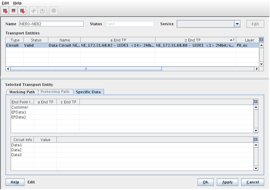
Selected Transport Entity: Specific Data
Please note:
By default three fields for Endpoint and Circuit Info can be used. The attributes can be renamed or enlarged as required. The adaptation must be done in the /opt/nem/etc/np.conf file. It is recommended to do the definition during the commissioning process of FOXMAN-UN NP.