
Starting the ‘Create CES’ Wizard
• Navigate to the Circuit Emulation Service tab:

• Use the “+ Create” action button:
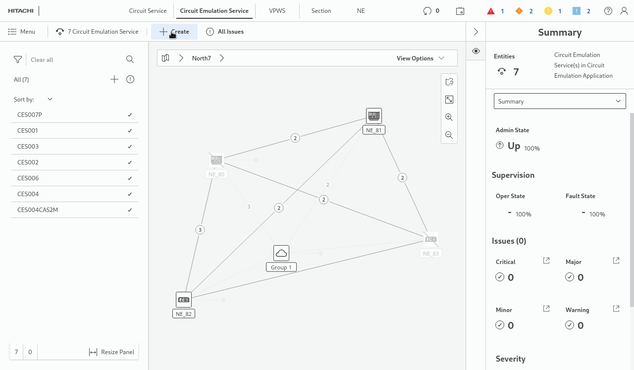
• The “Create CES” wizard dialog window appears in front of the CEM:
• Follow the steps in the “Create CES” wizard (bold parameters are mandatory and require user input).
1 General
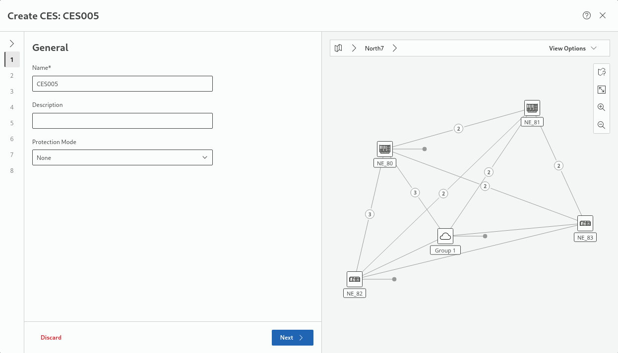
− Name - maximum 50 characters long. It should be descriptive but concise.
− Description – not required, optional field, maximum 50 characters long.
− Protection Mode - select from “None”, “1:1”. Default is “None”.
→ click “Next >” to proceed.
2 Endpoints
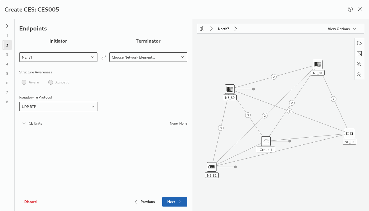
− Initiator and Terminator NEs.
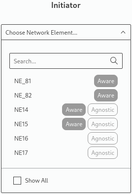
Please note:
Initiator and Terminator selectors are showing only those NEs which have at least one CE-capable unit, other NEs will not be shown. If required, for information purposes, non-suitable NEs can be included by activating the “Show All” option below the list.
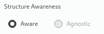
− Structure Awareness mode:
Please note:
Both Initiator and Terminator NEs must be equipped with a CE unit working in selected Structure Awareness Mode, i.e. the “Structure Awareness” mode must match the “CES Mode” in “Configuration - General” of the unit configuration (via FOXCST). If the two do not match, the unit cannot be selected as CE unit.
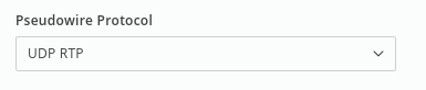
− Pseudowire Protocol:
- MEF8
- MEF8 RTP
- UDP
- UDP RTP
Please note:
The CEPI1 unit cannot operate in MEF8 and MEF8 RTP protocols at once; all Pseudowires configurations must use either of them.
− CE units selection; the user can see a list of available CE units on the selected NEs:
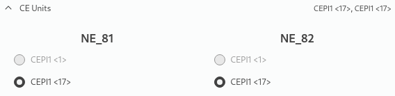
After Initiator and Terminator NEs are chosen, the wizard is automatically selecting the first applicable CE unit. If other units are available, you can select one of these if required.
Please note:
If the CE unit entry is disabled it might be due to selected Structure Awareness or Pseudowire Protocol which might not be supported by the CE unit in its current configuration.
→ click “Next >” to proceed.
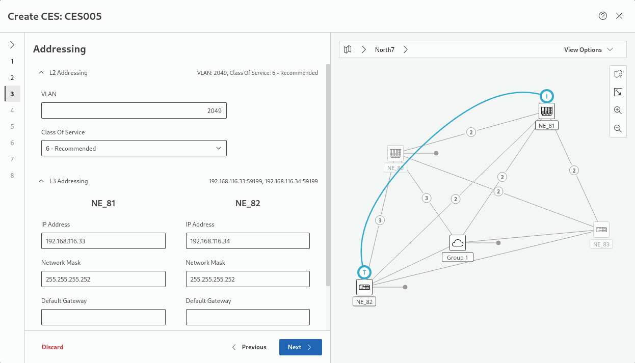
3 Addressing
Please note:
Addressing configuration is calculated automatically and should be changed only when necessary.
L2 Addressing provides automatically selected VLAN ID and Class Of Service parameters:
− VLAN - tag used to mark Ethernet frames which are carrying CE traffic. Used to differentiate traffic coming from other Network Services including other CE Services. Integer with a range 1 to 4089. Default value is proposed by CEM but its uniqueness is not guaranteed (current limitation).
− CoS (Class of Service): priority of packets carrying CE traffic:
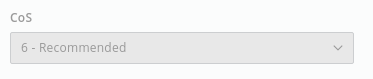
Available for selection: from 0 to 7. Value 6 is recommended.
L3 Addressing provides automatically selected IP addresses, network masks, default gatgeway (if required), and source UDP ports:
− IP Address: automatically set on both initiator and terminator.
− Network Mask: automatically set on both initiator and terminator.
− Default Gateway: automatically set; is left empty if not required.
− Source UDP Port: automatically set on both initiator and terminator.
If no service has been created on the unit, the source IP address can be overwritten in the wizard. If a service already exists, the source IP address cannot be modified (the input field is disabled).
Please note:
UDP addressing configuration is also necessary in case of Layer 2 Protocols (MEF8, MEF8 RTP).
− (MEF8, MEF8 RTP only) Destination MAC Address.
Please note:
Destination MAC Address should match Source MAC Address of second endpoint.
→ click “Next >” to proceed.
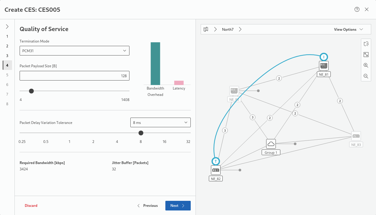
4 Quality of Service – Structure Aware mode
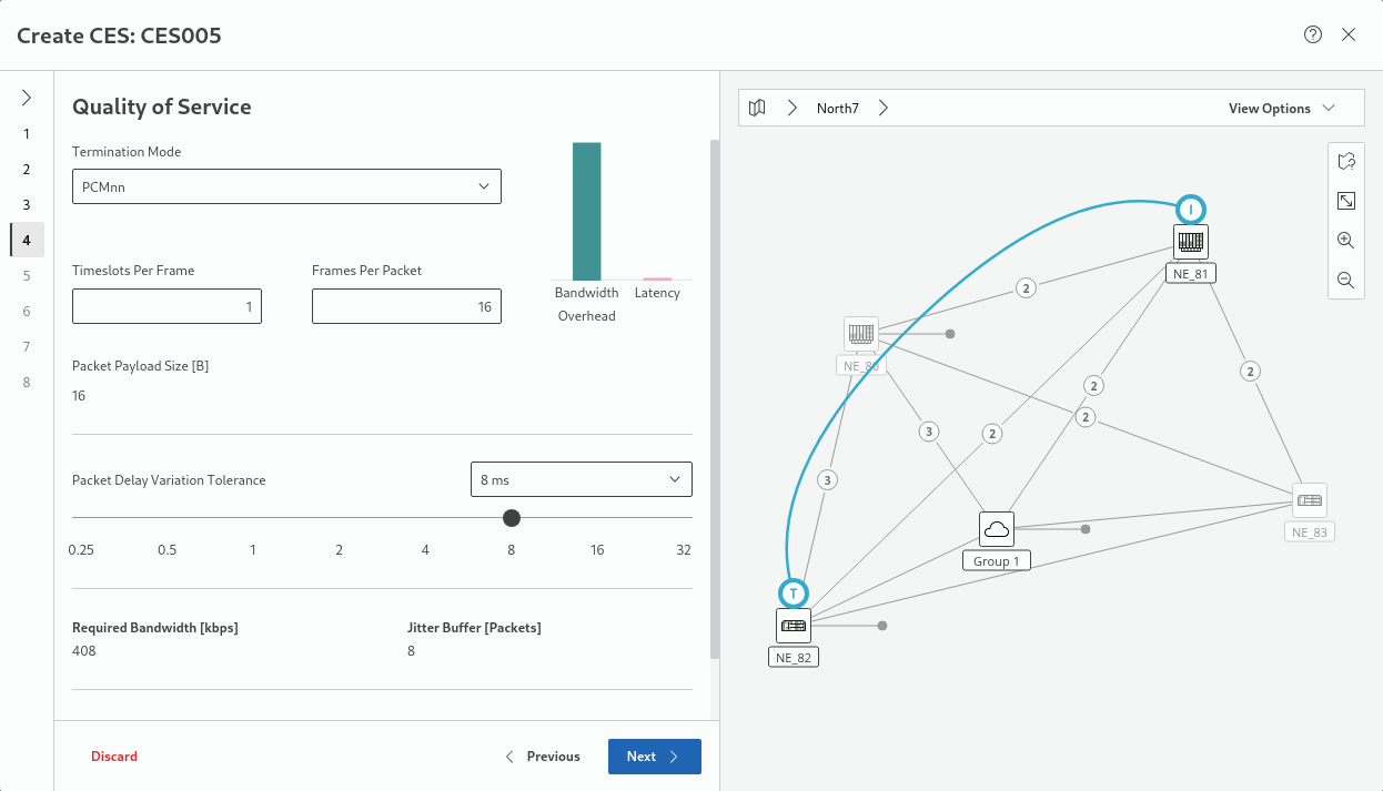
− Termination Mode; select from:
− PCMnn (nn concatenated 64 kbit/s timeslots, nn from 1 to max 31), default
− PCMnn CAS (nn concatenated 64 kbit/s timeslots with CAS, nn from 1 to max 30)
− PCM30 (30 concatenated 64 kbit/s timeslots)
− PCM30C (30 concatenated 64 kbit/s timeslots with CRC4)
− PCM31 (31 concatenated 64 kbit/s timeslots)
− PCM31C (31 concatenated 64 kbit/s timeslots with CRC4)
− Timeslots Per Frame: Integer in the range from 1 to 30, variable only in modes PCMnn and PCMnn CAS.
− Frames Per Packet: Integer in the range from 1 to 32. Check calculated Bandwidth Overhead and Latency bars to estimate suitability of selections.
− Packet Delay Variation Tolerance (PDVT):
− 0.25 ms,
− 0.5 ms,
− 1 ms,
− 2 ms,
− 4 ms,
− 8 ms,
− 16 ms,
− 32 ms;
Default is 8 ms; check calculated values of Required Bandwidth and Jitter Buffer.
Please note:
Calculated Jitter Buffer value needs to be in the range from 4 to 128 packets. In Structure Aware mode Jitter Buffer size depends on PDVT and Frames Per Packet values.
Please note:
Timeslots Per Frame and Frames Per Packet settings have influence on Bandwidth Overhead and Latency.
The “Bandwidth Overhead and Latency” chart is showing the relative influence of parameter changes on CES characteristics:
- Sending small packets often => Bigger overhead, lower latency;
- Sending big packets rarely => Lower overhead, bigger latency.
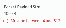
Please note:
The calculated Packet Payload Size must be in range from 4 to 512 Bytes. Payload size is a result of multiplication of Timeslots Per Frame and Frames Per Packet values.
− P12 containers on both ends.
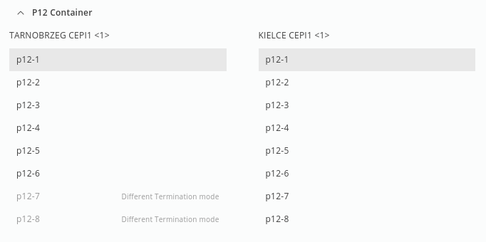
Shows a list of 8 available P12s on Initiator and Terminator CE units. Application selects automatically the first valid option.
Please note:
Particular P12 containers may be disabled due to several reasons:
→ P12 container is configured to operate with different Termination Mode from selected one (limitation, can be changed only via FOXCST).
→ Another Pseudowire which is using fixed timeslots Termination Mode (PCM30, PCM30C, PCM31, PCM31C) is already using that P12 container.
→ Current allocation of Timeslots in that P12 container does not allow to deploy new Pseudowire (only for variable timeslots Termination Modes PCMnn, PCMnn CAS).
− Timing:
− Clock Recovery Mode: Synchronous (default); Adaptive 1; Adaptive 2; Adaptive 3.
If Structure Awareness mode has been set to “agnostic” in step 2, Adaptive clock recovery mode needs to be selected.
− Filter: Filter 1; Filter 2; Filter 3; Filter 4 (default).
→ click “Next >” to proceed.
4 Quality of Service – Structure Agnostic mode
− Termination Mode:
− Transparent (transparent for clock and data)
− Clock Master (transparent data; retimed with the NE clock)
− PCM30 (30 concatenated 64 kbit/s timeslots)
− PCM30C (30 concatenated 64 kbit/s timeslots with CAS)
− PCM31 (31 concatenated 64 kbit/s timeslots), default
− PCM31C (31 concatenated 64 kbit/s timeslots with CAS)
− V5 Uplink (P12 signal terminated, retimed to NE clock, V5 specific Sa bit handling, with CRC4)
− V5 Uplink NCI (P12 signal terminated, retimed to NE clock, V5 specific Sa bit handling, without CRC4)
− Payload size – integer in the range from 4 to 1408. Affects Required Bandwidth and Jitter Buffer size.
− Packet Delay Variation Tolerance (PDVT):
− 0.25 ms
− 0.5 ms
− 1 ms
− 2 ms
− 4 ms
− 8 ms
− 16 ms
− 32 ms
Please note:
The calculated Jitter Buffer value needs to be in range from 4 to 128 packets. In Structure Agnostic mode Jitter Buffer size depends on PDVT and Packet Payload Size values.
Please note:
Timeslots Per Frame and Frames Per Packet settings have influence on Bandwidth Overhead and Latency.
The “Bandwidth Overhead and Latency” chart is showing the relative influence of parameter changes on CES characteristics:
- Sending small packets often => Bigger overhead, lower latency;
- Sending big packets rarely => Lower overhead, bigger latency.
→ click “Next >” to proceed.
5 Timing
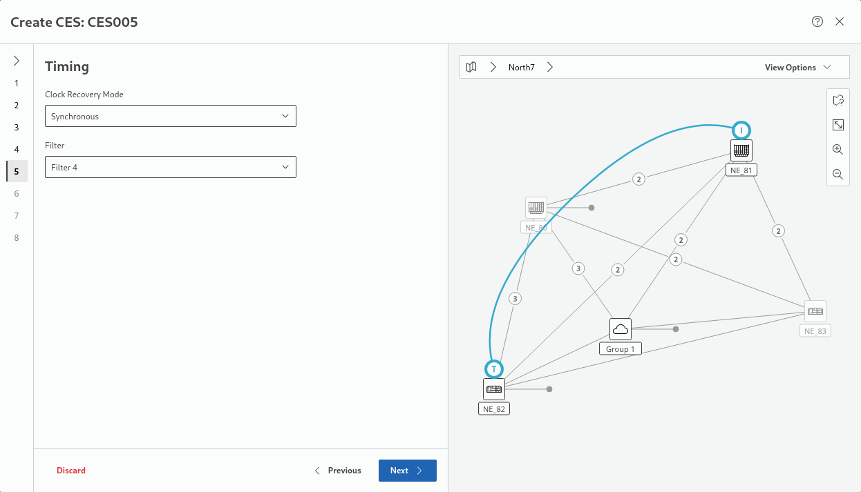
− Select the clock recovery mode from
− Synchronous (default)
− Adaptive 1,
− Adaptive 2,
− Adaptive 3.
− Select the filter from
− Filter 1,
− Filter 2,
− Filter 3,
− Filter 4.
→ click “Next >” to proceed.
6 Transport
− Select service profile from a list of appropriate service profiles;
The “Advanced” button allows you to view more service profile details (name, creation date, description, summary) and edit these as far as permissions are sufficient. For Service Profile requirements see section Prerequisites, “Transport Service requirements:”.
The service profiles can be filtered by class type via a click on the colored dots above the list. Service profiles with issues that prevent a selection can be included in the list by enabling “Show all” below the list. When selecting a service profile with issues, the reason for its non-eligibility is shown in the details area.
Please note:
In case of using Fixed Bandwidth Service Profile it must be able to ensure a bandwidth at least as big as the CES bandwidth calculated in the previous step.
− If required, modify the Bandwidth (kbps), provided the service profile allows that. It needs to be at least as large as the CES Bandwidth calculated in a previous step.
VPWS
A VPWS is either proposed if existing and suitable, or it will be created automatically.
Please note:
The VPWS service will be created using the default Protection setting from the Service Profile.
Attachment Circuit
An attachment circuit with its ports and port types will be proposed if existing and suitable, or it will be created automatically. The ports can be edited manually if required by clicking on the “Edit Port” buttons. The parameters are as foillows:
− Label 1,
− Label 2,
− Description,
− Port Type (PWAC, CVP),
− Admin State.
Any changes done to the ports must be deployed and will be applied immediately.
Please note:
VPWS will use Attachment Circuits of type “VLAN Based, No change with AC VLAN” with the same VLAN as configured in a previous step.
→ click “Next >” to proceed.
7 Tunnel
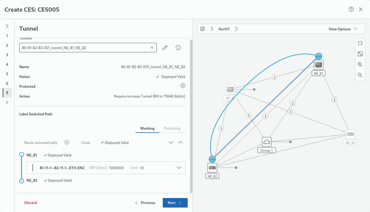
Usually shows a preselected tunnel if a suitable tunnel is available. In this case, “Action” might still indicate that the tunnel bandwidth needs to be increased if insufficient.
If there already is a proposed tunnel (in status Deployed Valid), the wizard will automatically perform the required actions. Alternatively, you may select a suitable tunnel manually or edit the tunnel to manually correct its properties. Take note of any possible proposed Action, such as, e.g., an increase of the tunnel bandwidth.
If no suitable tunnel is available, “New Tunnel” is shown and “Action” shows “Create new tunnel”. The new tunnel will automatically be created by the wizard.
To select an appropriate tunnel, click on the “Tunnel” drop-down field.
− Now you can use an existing tunnel (click radio button “Use existing tunnel”) and
− Change the tunnel,
− Refresh the tunnel, or
− Pick an existing tunnel.
− Or you can create a new tunnel that is more appropriate for your specific requirements under Label Switched Path by clicking the “Route atuomatically” settings icon to define the LSP auto routing parameters, such as
− routing order,
− max hops,
− max cost,
− excluded NEs,
− included NEs,
− excluded links.
When done with the auto routing parameters, click on “Apply”. Back in the wizard, click the “Route automatically” button which will create an LSP between the selected Initiator and Terminator NEs.
Do not forget to do this for both Working and Protecting LSP if protection is used.
The result will be indicated by the tunnel status “Unsaved”.
Please note:
In case auto-routing fails, it is recommended to launch ENP and create & deploy the tunnel(s) from there. Then in the CES wizard select them as existing tunnels.
− Make sure that all tunnel conflicts are resolved
→ click “Next >” to proceed.
8 Summary
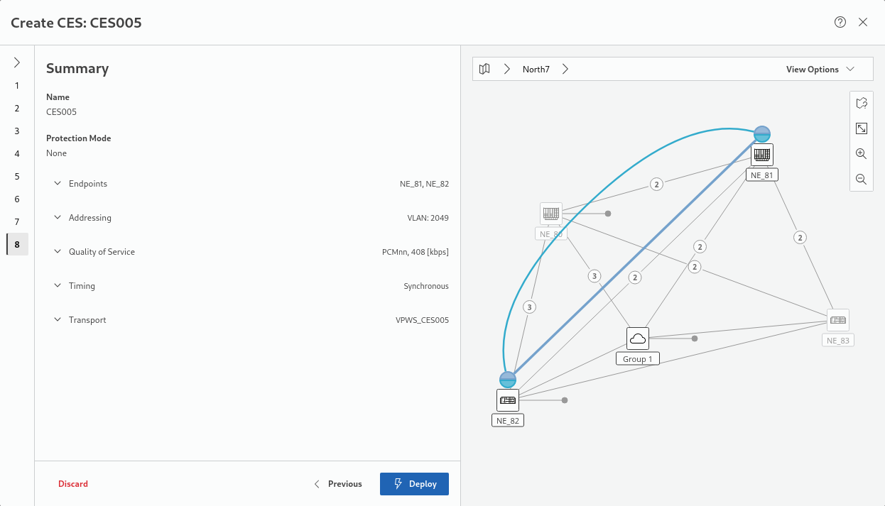
− Review and verify all settings specified in the previous steps, shown in the summary; if OK, click “Deploy”, otherwise go back to previous steps to make modifications before finishing.
Please note:
Invoking the “Deploy” action will trigger deployment of the CES to the network (no intermediate saved state is available). The Wizard will display details about the deployment process and its successful (or failed) sub-processes.
− Expected result: Once deployed, a confirmation is shown in the bottom right corner of the wizard:

− With the deployment confirmation in the summary, the action button will change to “Finish”. Click on the Finish button to close the wizard.
The resulting new service is listed in the Circuit Emulation Services overview table as soon as the service has been deployed and discovered from the network.