
Integration of a New Node
This chapter describes recommended procedures. Its contents are applicable to one sample use case out of many possible scenarios. In case of doubt, please contact technical support.
Assuming you have a circuit from port 4 on node 81 to port 4 on node 83, using an STM1 optical section between node 81 and node 83 (situation A in Figure Insertion of a new node (sample)). Now you want to insert a new node 82 into that optical section so that the circuit will be running from port 4 on node 81 via node 82 to port 4 on node 83 (situation B in Figure Insertion of a new node (sample)).
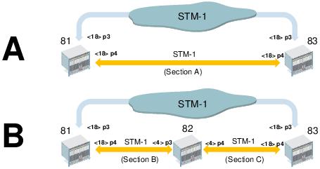
Insertion of a new node (sample)
Inserting a new node (82) into an existing Trail (or section A between node 81 and node 83, respectively) requires a procedure as follows. Note that this includes on-site intervention.
Recommended sample procedure for a FOX51x based network with SYN4E units.
Proceed as follows:
The following steps are taken off-site or on-site.
1. FOXMAN-UN/UCST: If you have protecting Trails or SNCs for the working section in which you need to insert the new node, switch the traffic over to the protecting Trails or SNCs. Also make sure you do not lose management access to nodes 81 and 83 when breaking section A in a later step.
2. UCST: Save the configuration of the nodes 81 and 83.
3. FOXMAN-UN NP: Get inventory of Transport Entities over the section A (use Section Editor, select section A, click “Open Circuit...” from the context menu, select the “Transport Entities” tab, and expand the “Section A” name). Make sure you are aware of all circuits and trails running over this section.
4. UCST: Create the configuration for the new node 82 with all required units, parameters and settings like synchronization, management communication channels (DCN), subunits/port configurations, cross connections, cabling, etc. Take into account the inventory of Transport Entities over the section A taken in previous step. Make the configuration file ready to be accessible when on-site.
5. UCST (optional): Enable Automatic Laser Shutdown and Automatic Laser Restart on the STM1 ports of nodes 81 and 83 if required for safety reasons.
The following actions are to be taken on-site (at node 82).
6. Physically open the section A (if configured, this will shut down the lasers, and operations can be executed without danger). Insert node 82, i.e. connect fibers to create section B and section C.
7. UCST: Locally connect to node 82 and download the configuration created in step 4 of the current procedure.
8. UCST: If required perform an ALS (Automatic Laser Shutdown) Manual Restart on the physical section for the subunits on nodes 81 and 83.
9. Make sure the ports’ operational state is up.
The following actions are taken off-site, but may require on-site intervention.
10. FOXMAN-UN: Add node 82 to FOXMAN-UN (basic procedure).
11. FOXMAN-UN: Check management connectivity; if not working, on-site action may be required to correct this.
12. FOXMAN-UN Section Manager: Delete section A.
13. FOXMAN-UN Section Manager: Create section B between node 81 and node 82; create section C between node 82 and node 83 (see situation B in Figure Insertion of a new node (sample)).
14. FOXMAN-UN NP: Add node 82 to the NP Domain.
15. FOXMAN-UN NP: The new circuit is created automatically.
16. FOXMAN-UN NP: Check that all Transport Entities are set up as expected, and their individual status is valid.
17. After verification of all changes, switch the traffic back from protecting Trails or SNCs to the working ones if required.
If manual creation of cross connections in UCST as in step 4 above is not wanted, the original circuits can be re-routed automatically or manually in FOXMAN-UN NP. This procedure may be preferred if manual creation of cross connections with UCST is unwanted.
In the above procedure, after having added the node 82 to the NP domain (step 14), depending on the trails listed in step 3 above, you will have to add VC4 and VC12 trails between nodes 81 and 82, and between nodes 82 and 83 to enable routing of circuits.
End of instruction
Recommended sample procedure for an FOX61x based network with SAMO1 units.
Proceed as follows:
1. FOXMAN-UN/FOXCST: If you have protecting Trails or SNCs for the working section in which you need to insert the new node, switch the traffic over to the protecting Trails or SNCs. Also make sure you do not lose management access to nodes 81 and 83 when breaking section A in a later step.
2. FOXMAN-UN/FOXCST: Make backup of nodes 81 and 83 (save configuration to disk).
3. FOXMAN-UN NP: Get inventory of Transport Entities over the section A (use Section Editor, select section A, click “Open Circuit...” from the context menu, select the “Transport Entities” tab, and expand the “Section A” name). Make sure you are aware of all circuits and trails running over this section.
4. FOXCST (standalone version): Create offline configuration for the new node 82 with all required units, parameters and settings like synchronization, management communication channels (DCN), port configurations, cross connections, cabling, etc. Take into account the inventory of Transport Entities over the section A taken in previous step.
5. FOXCST (standalone version): Save offline configuration for node 82 to disk. Make the configuration file ready to be accessible when on-site.
The following action is to be taken immediately before on-site intervention.
6. FOXMAN-UN: Disable section A by putting the section A ports on nodes 81 and 83 to admin state “down” (this will shut down the lasers, and operations can be executed without danger).
The following actions are to be taken on-site (at node 82).
7. Physically open the section A and insert node 82 (i.e. connect fibers to create section B and section C).
8. FOXCST: Locally connect to node 82 and download the configuration created in step 4 of the current procedure.
9. FOXCST: Enable sections B and C by settings the admin state of ports on nodes 81 and 83 to “up”. Make sure the ports’ operational state is up.
The following actions are taken off-site, but may require on-site intervention.
10. FOXMAN-UN: Add node 82 to FOXMAN-UN (basic procedure).
11. FOXMAN-UN: Check management connectivity; if not working, on-site action may be required to correct this.
12. FOXMAN-UN Section Manager: Delete section A.
13. FOXMAN-UN Section Manager: Create section B between node 81 and node 82; create section C between node 82 and node 83 (see situation B in Figure Insertion of a new node (sample)).
14. FOXMAN-UN NP: Add node 82 to the NP Domain.
15. FOXMAN-UN NP: The new circuit is created automatically.
16. FOXMAN-UN NP: Check that all Transport Entities are set up as expected, and their individual status is valid.
17. After verification of all changes, switch the traffic back from protecting Trails or SNCs to the working ones if required.
End of instruction