
Change of Sections
This chapter describes recommended procedures. Its contents are applicable to one sample use case out of many possible scenarios. In case of doubt, please contact technical support.
Changing a layer rate on a section between two nodes requires that the section carrying the trails/circuits is removed in FOXMAN-UN between the two nodes, and a new section is added. With a FOX51x node (SYN4E units for optical sections) the recommended procedure e.g. for changing the physical layer rate from STM-1 to STM-4 is as shown in the first example. The second example describes the recommended procedure for FOX61x nodes with SAMO1 units.
The examples assume nodes 81 and 83, and section A (STM-1) between the two nodes. Refer to Figure Change of section layer rate (sample) where the two situations A (section with STM-1 layer rate) and B (same section, now with STM-4 layer rate) are shown.
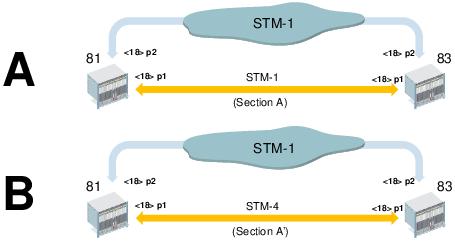
Change of section layer rate (sample)
Recommended sample procedure for FOX51x nodes equipped with SYN4E units
Sample procedure for FOX51x nodes equipped with SYN4E units. Note that this requires on-site intervention if single-rate SFP modules are used. Also note that disabling the subunits, and re-enabling them after changing the layer rate may not be required, depending on the preferred on-site procedure.
Proceed as follows:
1. FOXMAN-UN / UCST: Get (and print) an inventory of VC4 layer cross connections on node 81. Take appropriate measures not to lose management access to nodes 81 and 83 when re-configuring section A.
2. FOXMAN-UN / UCST: Disable the STM1 subunit providing the physical port to section A of node 81. This will disable the physical port and remove the cross connections of that subunit on node 81.
3. FOXMAN-UN / UCST: On the same subunit change the physical section “Type” from “STM1” to “STM4”. Enable the subunit.
4. FOXMAN-UN / UCST: Re-create the VC4 layer cross connection(s) for this STM4 subunit in node 81. Do not yet download the configuration to the node.
5. FOXMAN-UN / UCST: Get (and print if required) an inventory of VC4 layer cross connections on node 83.
6. FOXMAN-UN / UCST: Disable the STM1 subunit providing the physical port to section A of node 83. This will disable the physical port and remove the cross connections of that subunit on node 83.
7. FOXMAN-UN / UCST: On the same subunit change the physical section “Type” from “STM1” to “STM4”. Enable the subunit.
8. FOXMAN-UN / UCST: Re-create the VC4 layer cross connection(s) for this STM4 subunit in node 83. Do not yet download the configuration to the node.
The following action is to be taken immediately before on-site intervention.
9. FOXMAN-UN / UCST: Download the configurations to node 81 and to node 83. If you do not have remote management access with interrupted section A take the configuration files on-site for local configuration download.
The following actions are to be taken on-site (with single-rate SFPs).
10. On both node 81 and node 83 unplug the fibers on the front port that is to be changed from STM-1 to STM-4.
11. Replace the STM-1 SFP modules by STM-4 SFP modules.
12. Re-connect the fibers on the front port of node 81 and on the front port of node 83.
The following actions are taken off-site, but may require on-site intervention.
13. FOXMAN-UN: Delete section A with old layer rate between node 81 and node 83.
14. FOXMAN-UN: Create section A’ with new layer rate between node 81 and node 83.
15. FOXMAN-UN NP: Verify that all Transport Entities of the new section are listed correctly, and their status is valid.
End of instruction
Recommended sample procedure for FOX61x nodes equipped with SAMO1 units
The following is a recommended sample procedure for FOX61x nodes equipped with SAMO1 units; note that this requires on-site intervention if single-rate SFP modules are used. Also note that setting the admin state of the ports to down, and to up again after changing the layer rate may not be required, depending on the preferred on-site procedure.
If single-rate SFPs are used the following action is to be taken immediately before on-site replacement of the STM-1 SFP modules by STM-4 SFP modules; with multi-rate SFPs on-site intervention may not be required.
Proceed as follows:
1. FOXMAN-UN/FOXCST: Get (and print) an inventory of VC4 layer cross connections on nodes 81 and 83. Create backup files for nodes 81 and 83. Take appropriate measures not to lose management access to nodes 81 and 83 when re-configuring section A.
2. FOXMAN-UN/FOXCST: Optional: Set the admin state to “down” for the STM1 port to section A of node 81.
3. FOXMAN-UN/FOXCST: On the same port change the PS “Port Mode” from “STM1” to “STM4”. The VC4 cross connection on that port on node 81 will remain.
4. FOXMAN-UN/FOXCST: Optional: Set the admin state to “down” for the STM1 port to section A of node 83.
5. FOXMAN-UN/FOXCST: On the same port change the PS “Port Mode” from “STM1” to “STM4”. The VC4 cross connection on that port on node 83 will remain.
The following actions are to be taken on-site (with single-rate SFPs).
6. On both node 81 and node 83 unplug the fibers on the front port that is to be changed from STM-1 to STM-4.
7. Replace the STM-1 SFP modules by STM-4 SFP modules.
8. Re-connect the fibers on the front port of node 81 and on the front port of node 83.
The following actions are taken off-site, but may require on-site intervention.
9. FOXMAN-UN/FOXCST: Optional (to be done if admin state has been set to “down” before): Set the admin state to “up” for the STM4 ports on node 81 and on node 83.
10. FOXMAN-UN: Delete section A with old layer rate (STM1 PMS) between node 81 and node 83.
11. FOXMAN-UN: Create section A’ with new layer rate (STM4 PMS) between node 81 and node 83.
12. FOXMAN-UN NP: Verify that all Transport Entities of the new section are listed correctly, and their status is valid.
End of instruction