
Starting the “Create Teleprotection Service” Wizard
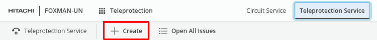
• Navigate to the Teleprotection Services tab:

• Use the “+ Create” action button:
• The “Create Teleprotection” wizard dialog window appears in front of the Teleprotection Service table and/or map.
• Follow the steps in the “Create Teleprotection” wizard (bold parameters are mandatory and require user input).
The Teleprotection service wizard guides you through service creation in 7 main steps as shown in the following sample.
Step 1 General
In step 1 “General” you need to provide basic service identification including
• Name
• Description (optional)
• Teleprotection Type (Differential; Distance; GOOSE/SV)
• Protection Mode (None; 1:1 (not recommended); Hitless)
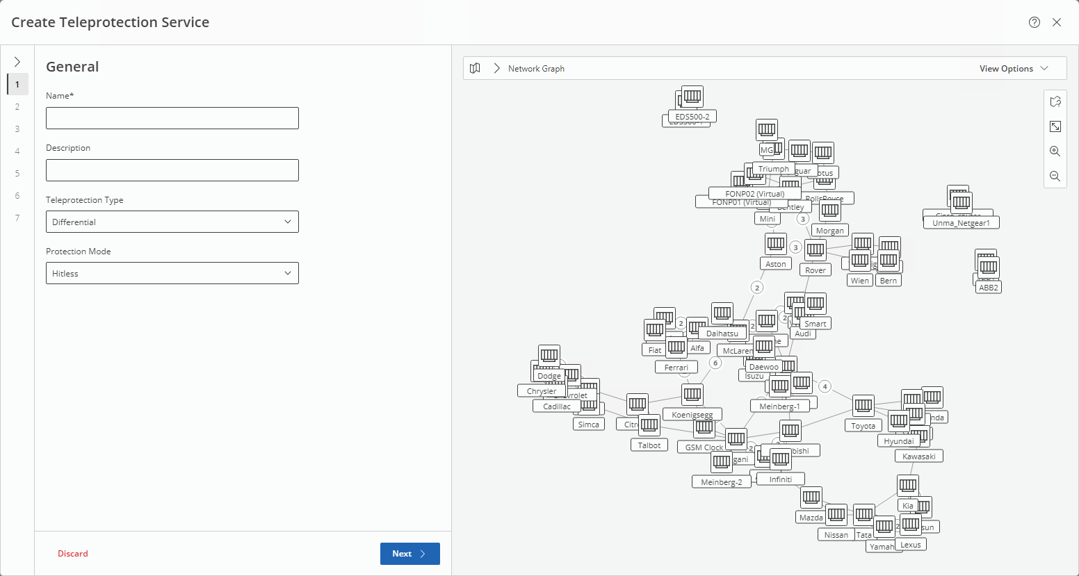
Teleprotection Type and related Protection Modes have some dependencies and will also restrict their applicability to certain NEs and the units in operation on these NEs. Also see step 2.
Click “Next >” to proceed to step 2 “Endpoints”.
Step 2 Endpoints
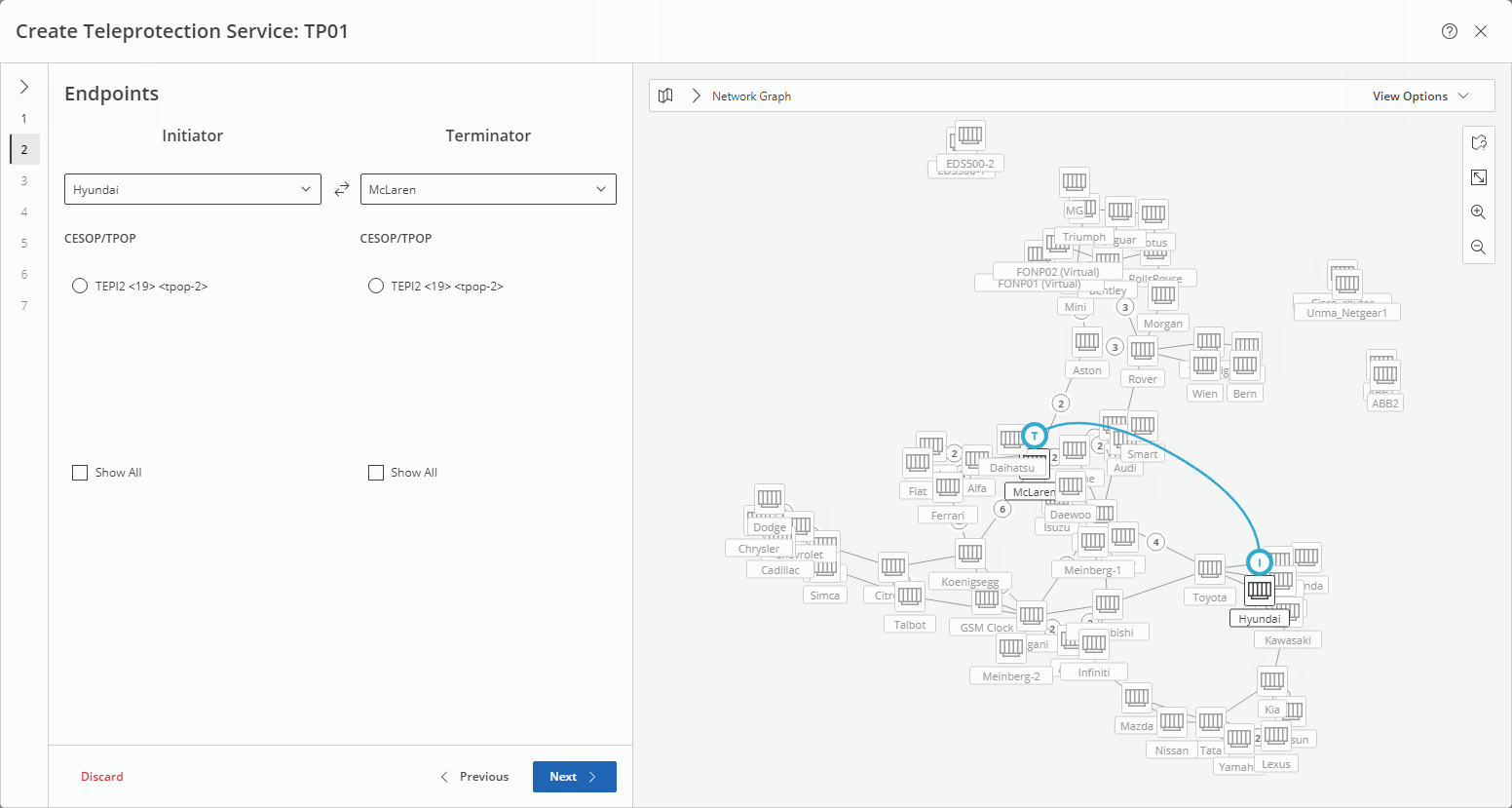
Select an Initiator NE and a Terminator NE. If no suitable NEs are available due to their provisioning with appropriate units supporting the chosen teleproction type and/or protection mode, you can click on “Show All” at the bottom of the selection list to include NEs that would provide teleprotection service features, but do not support the required combination of teleproction type and protection mode. Initiator and Terminator NE and the service connection are marked on the map.
If suitable NEs are selected, select the unit ports you want to use for the service. Use the “Show All” option for each NE to include units/ports that provide support for teleprotection services but are not available for selection, e.g., because they are already carrying such a service.
Once unit ports are selected, a proposed port configuration is added for both NEs with their preselected termination modes. If required, you can select a different termination mode from the drop-down list.
Click “Next >” to proceed to step 3 “Addressing”.
Step 3 Addressing
Step 3 proposes preselected settings for
• L2 addressing, transport 1;
• L2 addressing, transport 2;
• L3 addressing.
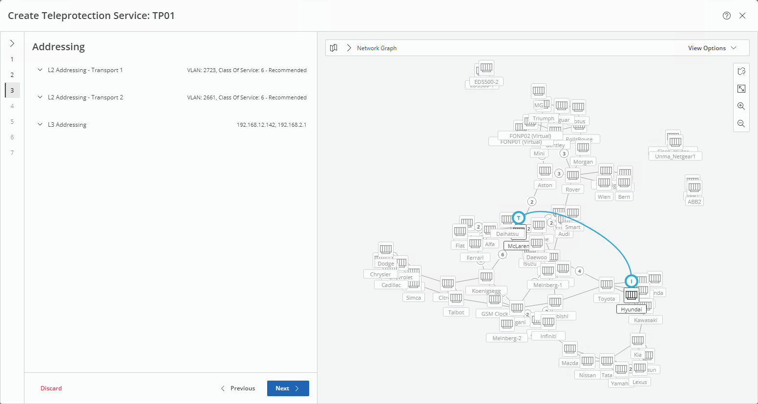
You can expand each of the characteristics to view the details and modify them if required. Note that some of the settings (e.g., L3 source IP addresses), if modified, need further actions to ensure a working service.
Click “Next >” to proceed to step 4 “Quality of Service & Timing”.
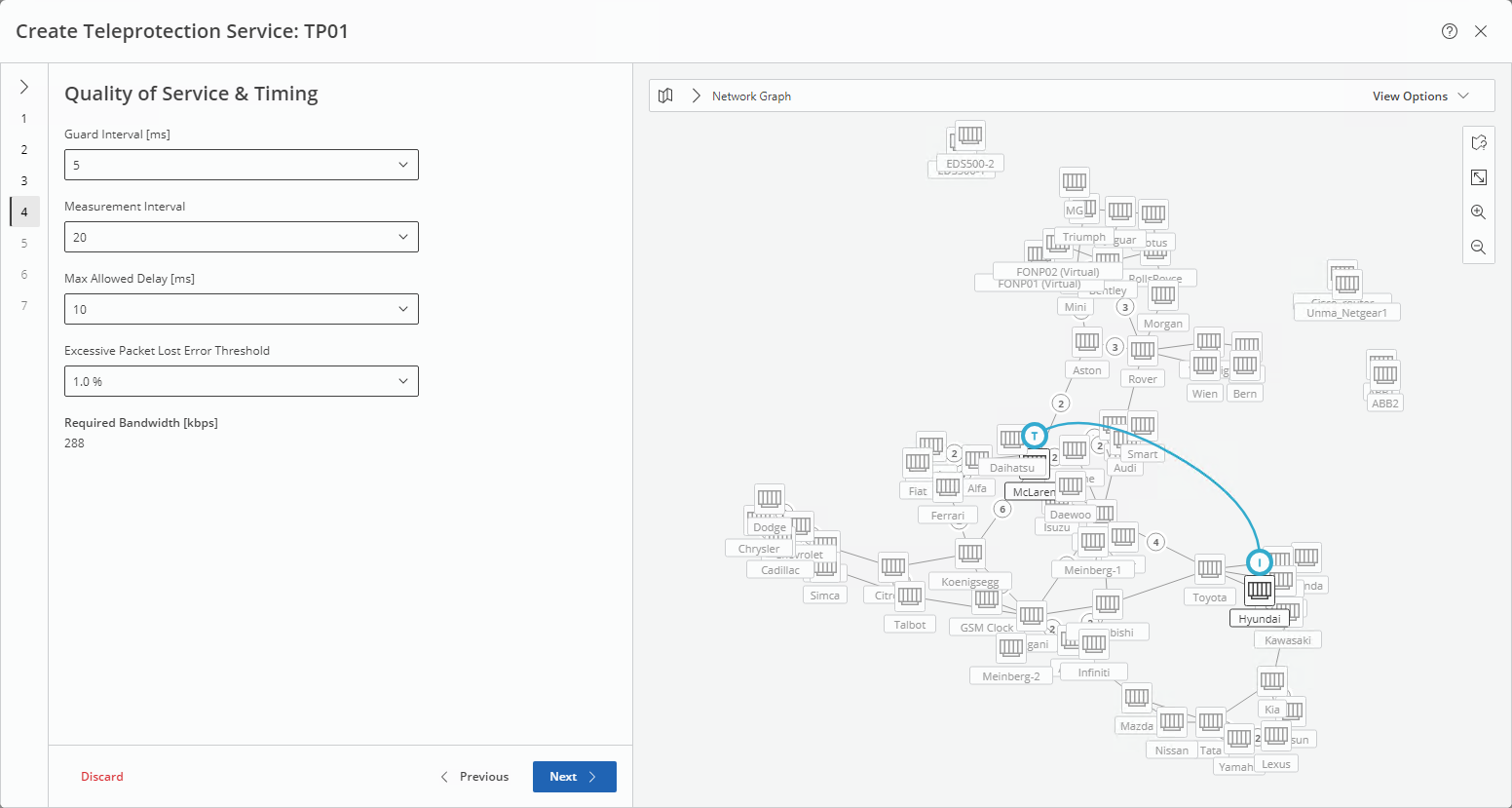
Step 4 Quality of Service & Timing
Depending on the service type, select the requied settings for
• Guard Interval
• Measurement Inteval
• Max Allowed Delay
• Excessive Packet Loss Error Threshold
or select the requied settings for
• Frames Per Packet
• E2E Transmission Delay
• E2E Transmission Delay Threshold
• Sync Supervision:
− GMs Locked by GPS
− GMs Locked by GPS Or GM IDs Match
− GMs Locked by GPS And GM IDs Match
− GM IDs Match
− None (Sync Supervision Disabled)
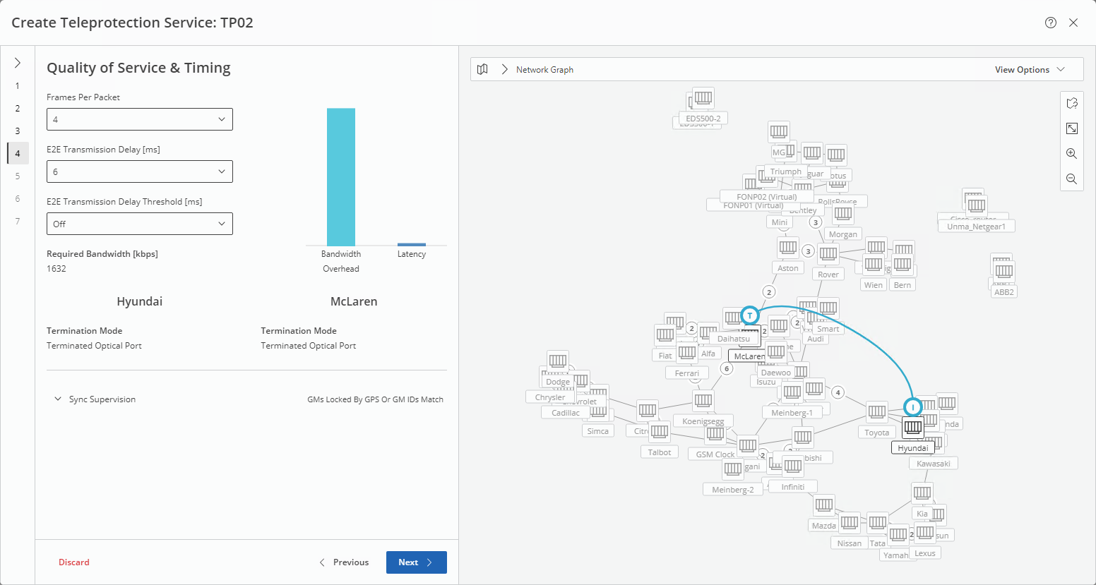
or accept the proposed QoS and timing settings. The required bandwidth is automatically calculated and displayed.
Click “Next >” to proceed to step 5 “Transport”.
Step 5 Transport
Select the appropriate service profile from the list of available service profiles. Click “Show All” to include service profiles in the list that are unsuitable for the selected service charcteristics.
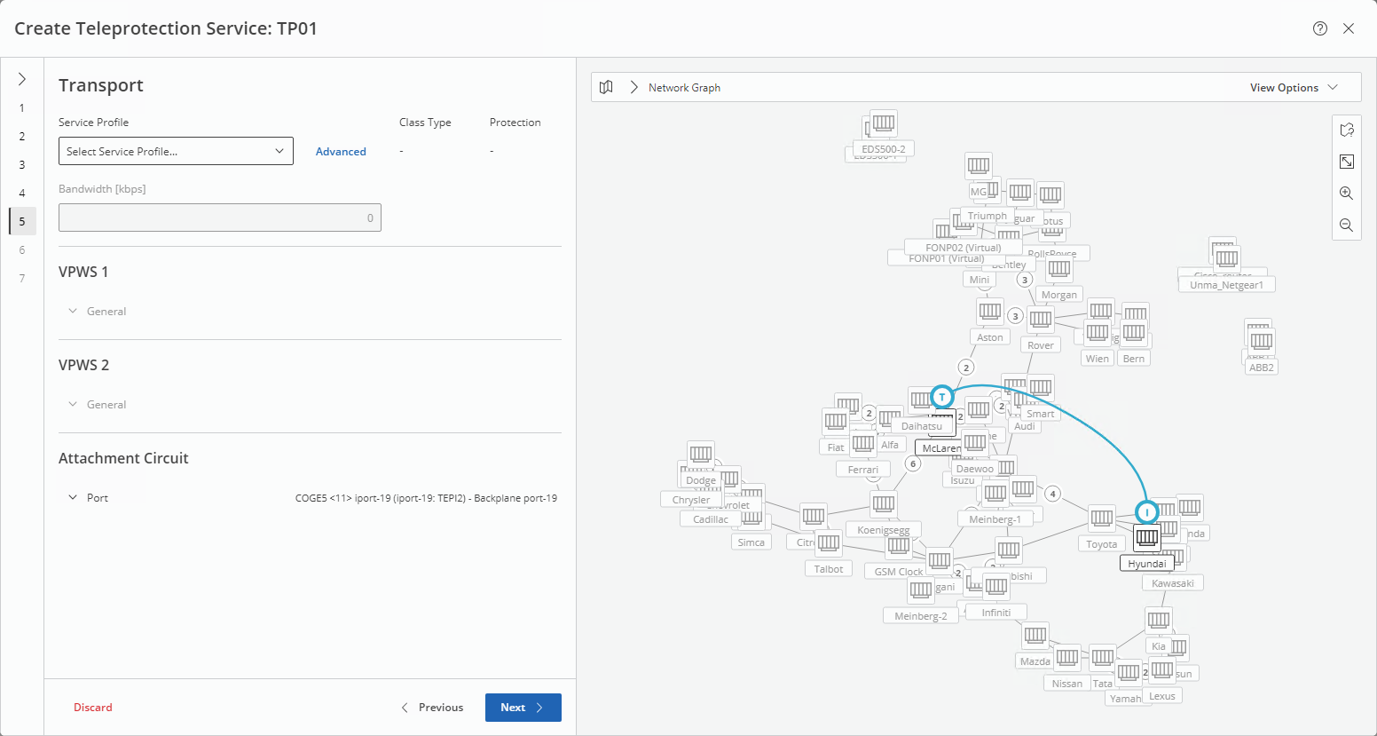
Once a suitable service profile is selected, the Class Type color, protection support, bandwidth, appropriate VPWS 1 and VPWS 2 and the AC (attachment circuit) are porposed if avilable.
The bandwidth can be modified if required.
The attachment circuit (AC) ports can be edited if required. Their port type is shown when expanding the port name using the expand arrow. Port changes need to be deployed and will take effect immediately, i.e. before service deployment.

If none are available they need to be created before proceeding.
Click “Next >” to proceed to step 6 “Tunnel”.
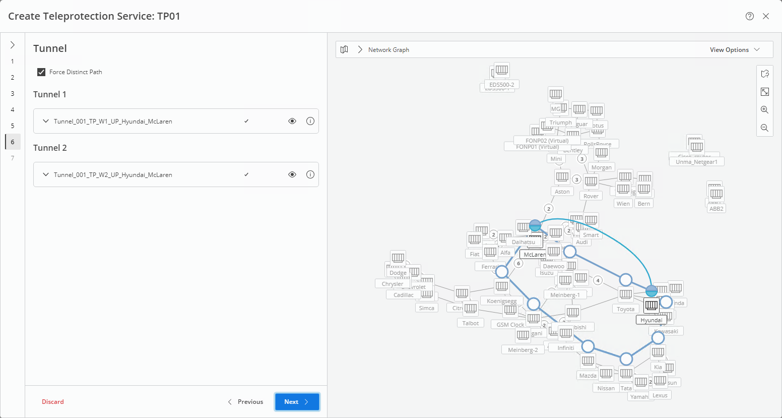
Step 6 Tunnel
If appropriate tunnels already exist, their names are proposed as “Tunnel 1” and “Tunnel 2”. The tunnels also appear on the map.
In case of disabling the “Froce Distinct Path” option, only one tunnel is proposed.
If no appropriate tunnels exist, a new tunnel must be created for each path before proceeding. New tunnels can be routed manually or automatically.
If a selected tunnel needs to be modified before applying it for the service, click on the pen icon right to the tunnel name and make the necessary changes. The “info” icon right to the tunnel name shows detailed information about the selected tunnel.
If protection shall be applied, make sure to define a tunnel for both Working and Protecting path.
Click “Next >” to proceed to step 7 “Summary”.
Step 7 Summary
The summary will show tha main service characteristcs specified in the different steps. Details can be shown by expanding the inidivdual step sections
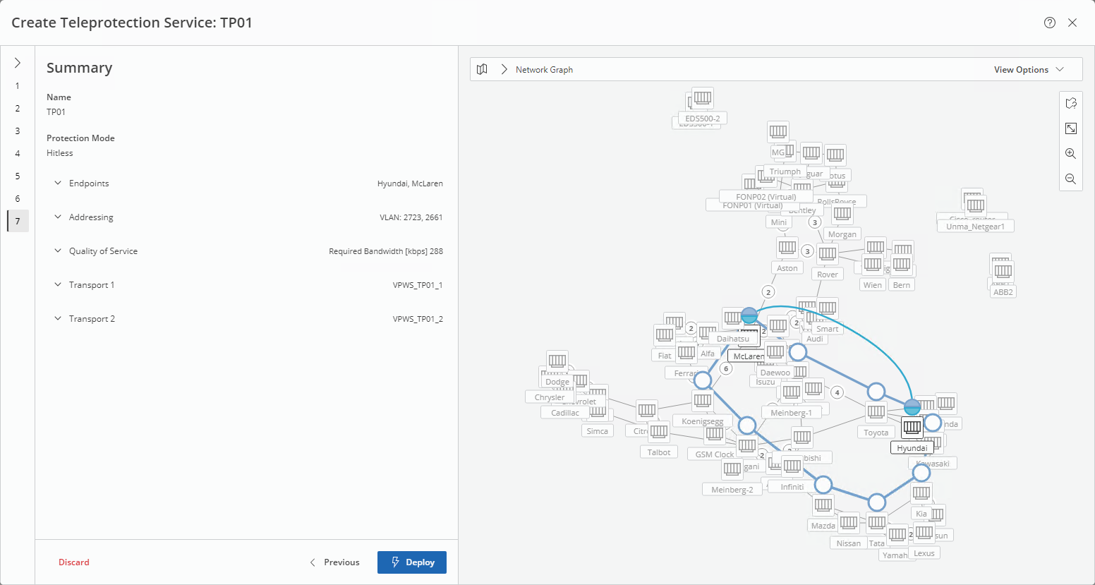
Click “Deploy” to deploy the service to the network.
Once deployed successfully, click “Finish” to close the wizard.
→ The new service will now be listed in the Teleprotection Service table and, upon selection in the list, will be highlighted in the map.