
Circuit Provisioning Processes
Please note:
The provisioning example described in this section assumes the following:
• NP database is initialized,
• NP/BP databases are synchronized,
• No pending changes indications,
• No application conflict detected.
In case of any of the above listed issues, please refer to section 4.2 “NP User Work Flow” of “Networking Package User Manual” [1KHW002416].
1 Check the prerequisites for running NP
− Check the FOXMAN‑UN Release Note if all parameters regarding network size and WS type have been set as recommended.
− Ports must be linked with Sections (via Section Management).
− Unit and Port (Sub-Unit) parameters should already be configured via CST.
− Verify that the current user has access rights to the Networking Package user Privileges and Domain Access to NP-Nodes Domain:
NEM Desktop > NEM Configurator > Security > Users > “User” > User Properties
“NP Open Access”: the operator can launch the FOXMAN‑UN NP user interface and browse the content of the network.
“NP Update Access”: the operator can make modifications.
“Domain Access”: NP nodes.
− Networking Package is supported in the License. The number of supported NEs of each type should likewise be defined:
$ lslicense
− Ensure that NP Network Manager Daemon is running:
$ lscore or via Remote Admin Tool
− Ensure correct interworking of BP and NP databases, run the script:
$ npresynch
Note:
Ensure that the user is not logged in to the NEM Desktop.
− Ensure that all NEs to be reported to NP are members of the automatically generated NP-Nodes Domain.
Add Members to NP-Nodes Domain via:
NEMDesktop > Application > NEM Configurator > Domains > right click on “NP-Nodes” > Domain Properties > Change Selection > Choose Members
Please note:
To enable the option to automatically add the subsequently discovered/created NEs, add the parameter below to /opt/nem/etc/nem.conf:
np_add_ne_to_domain true
2 Call the NP Main Window via:
NEM Desktop > Application > Networking Package…
3 (Optional) Create Application Filter.
− The “All” filter is created by default. A new filter can be created via:
NP main Window menu: File > Create
− Select the filter, and Retrieve the filtered Applications.
4 (Optional) Define Automatic Routing Parameters via:
NP Main Window menu: Options > Set Auto Routing Parameters…
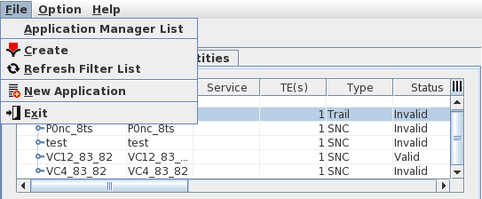
5 Create a New Application by calling the Application dialog:
NP main Window menu: File > New Application
or Edit an existing Application via its context menu: “Details”.
6 From the Application dialog, click the “Edit” button (Note: New Application dialog is automatically in Edit mode), or edit an existing Application via its context menu “Edit”.
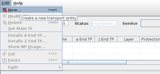
7 For a new Application call the New TE dialog via:
menu Edit > New
or via the context menu “New”
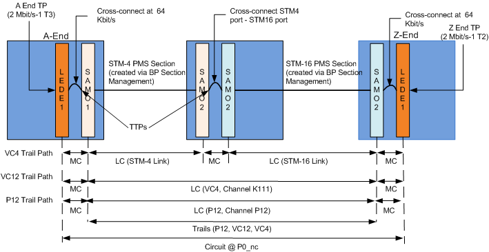
8 Create New TEs by specifying the following between A End and z End NEs:
− VC4 Trail
− V12 Trail
− P0_nc Circuit
9 Click OK to go back to Application dialog.
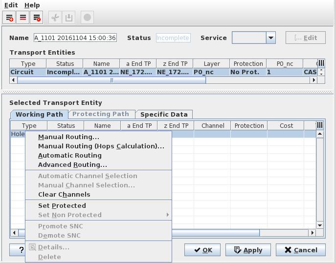
10 Select the new TEs and select the route: Manual Routing, Automatic Routing or Advanced Routing.
11 Routing
• If Automatic Routing is selected, the NP completes the Route based on the user’s configured Automatic Routing Parameters.
• If Advanced Routing is selected,
− Set the parameters “Maximum Hops”, “Maximum Cost”, and “Routing Order”.
− As required, select NEs to be avoided and Rates (i.e. physical or logical layer rates) to be avoided while routing.
− When ready, click on the “Route” button.
• If Manual Routing is selected,
− Select the Next Hop from the list. Click Apply.
− Repeat the process until the Path is complete. Select the Final Hop, and click OK.
− The Selected Transport Entity: Working Path details shows list of LC(s). The Channel(s) is “undefined”. Right Click and select “Automatic Channel Selection”.
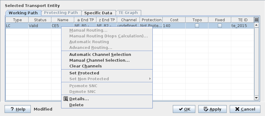
− The next available timeslot is selected for the path and required MCs are displayed, with Status “Waiting”.
− Click the Apply button. NP Commits the configuration to the network. Configuration changes are made and automatically downloaded/applied to the Nodes.
− When Status becomes “Valid” the circuit is created. Note the Channel selected (e.g. T1) is displayed.
− Click the entry “LC” and right click “Details” to see the Trails’ details.
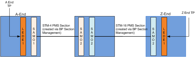
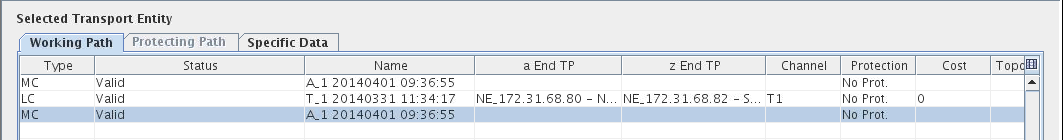
The provisioned circuit and details are shown in the diagram below:
12 Click “Cancel”, then “OK” to go back to NP main menu.
13 Select the Filter and click context menu “Retrieve” to view the new Application.