
Overview of VPLS Implementation
Virtual Private LAN Service (VPLS) is a multipoint-to-multipoint Ethernet bridging service over an MPLS-TP network. All customer sites connected to the same VPLS instance appear to be in the same Local Area Network (LAN).
VPLS is based on fully meshed MPLS-TP network architectures. H-VPLS is solving scalability issues by introducing spoke Pseudo Wires. Both VPLS and H-VPLS are listed in the same hierarchical table in the ENP.
VPLS Components
The FOX61x which acts as VPLS node has an Ethernet switch with VLAN support. This function is implemented on the core unit(s) and on the Ethernet service units. All switch elements implemented on the core unit and Ethernet service units are interconnected via the GbE or the 10 GbE star. Together they constitute one bridge instance.
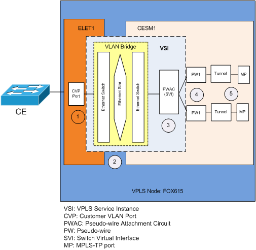
1 The Bridge port is the Ethernet service unit port with port type set to “CVP” (Customer VLAN Port). Any port configured as CVP connects to the VLAN bridge. This port accepts VLAN tagged or untagged user traffic.
2 VLAN Bridge component handles the local VLAN provisioning. These include the local VLAN creation, bridge port VLAN membership configurations and bridge port mode setting. These configurations are done via FOXCST. If the user specifies a non-existing VLAN when creating VPLS, the ENP automatically creates this VLAN.
Please note:
For more details please refer to Ethernet Switching User Manual [1KHW028566].
The bridge ports can be attached to the (H-)VPLS service if it shares the same VLAN ID with the corresponding Switch Virtual Interface (SVI).
The FOX61x supports the following bridge port modes on the chassis switch:
− Access ports mode:
The access port’s ingress direction accepts only untagged or priority tagged frames, which become tagged with port VLAN ID (PVID). The PVID must be member of the bridge VLANs.
− Q-in-Q port mode:
The Q-in-Q port’s ingress direction accepts all frames, be they VLAN tagged or untagged. The frames become tagged with the port VLAN-ID (PVID), e.g. untagged ingress frames become single tagged, single tagged ingress frames become double tagged. The PVID must also be member of the bridge VLANs.
− Trunk port mode:
The trunk port’s ingress direction accepts tagged frames whose VLAN ID is member of the bridge VLANs. Untagged or priority tagged frames are dropped. Inside the chassis switch, the frames keep their VLAN-ID. Note that the trunk port has no PVID. This port mode is not suitable for VPLS services.
− Trunk with Native VLAN mode:
The trunk with native VLAN port’s ingress direction accepts tagged frames whose VLAN ID is member of the bridge VLANs. Untagged or priority tagged frames are tagged with PVID. The PVID must be member of the bridge VLANs. This port mode is not suitable for VPLS services.
− General port mode:
The general port’s ingress frame handling is defined by the “Acceptable Frametype” and “Ingress Filtering” settings.
A general port provides a VLAN membership table. When “Ingress Filtering” is enabled, the general ingress port drops all Ethernet frames whose VLAN ID is not listed in the VLAN membership table.
Acceptable Frametype | Ingress Filtering | Description |
|---|---|---|
Untagged and Priority Tagged | Disabled | General port acts like access port. |
Enabled | General port acts like access port, drops frames whose VLAN ID is not member of the VLAN membership table. | |
Tagged | Disabled | General port acts like trunk port. |
Enabled | General port acts like trunk port, drops frames whose VLAN ID is not listed in the VLAN membership table. | |
All | Disabled | General port acts like trunk with native VLAN port. |
Enabled | General port acts like trunk with native VLAN port, drops frames whose VLAN ID is not listed in the VLAN membership table. |
3 Switch Virtual Interface (SVI)
The SVI is the attachment circuit (AC) of a (H-)VPLS. The SVI is automatically created by ENP and its VLAN ID mapped to the local VLAN ID. That is, SVI VLAN ID = local VLAN ID.
VPLS instance, VPN OUI:
The SVI associates the SVI VLAN with one (H-)VPLS Service Instance (VSI) identified by VPN ID (VPN OUI). The unique VPN OUI is calculated by ENP and is set up on all NEs participating in the VSI.
The VSI is composed of the Pseudo Wires belonging to the respective (H-)VPLS instance. The (H-)VPLS instance forwards the SVI VLAN tagged user traffic to all these Pseudo Wires.
4 Pseudo wires are created automatically to achieve full mesh connectivity between all VPLS nodes.
The figure below shows that three Pseudo Wires (PW1, PW2, PW3) are created to connect all the three VPLS nodes.
The endpoints AC type is strictly dependent on the local VLAN configuration (VID ETH) on the node. All Pseudo Wires with the VPLS Service will be set up between SVIs with the PWAC VLAN Based type. However, the local VLAN ID used on every node maybe different. In that case the PW VLAN rewriting on both sides is required (Stack B). Otherwise, no PW VLAN rewriting is needed (Stack A).
The PW VLAN ID of each Pseudo Wire attached to SVI are controlled using the VLAN Mode:
− AC Type VLAN-Based, No Change (Stack A):
The PW VLAN ID is the same as the SVI (AC)VLAN ID: VID <ETH>.
− AC Type VLAN-Based, Change VLAN (Stack B):
The SVI (AC) VLAN ID is modified to a new PW VLAN ID: VID <PW>.
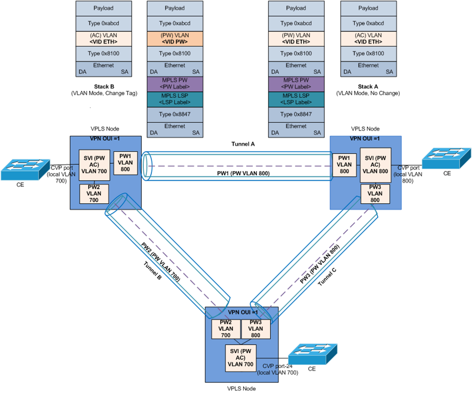
5 The control unit (CESM1, CESM2 or CESM3) encapsulates the PW VLAN tagged frames into MPLS-TP frames by adding the PW label, the LSP label and the Ethernet destination and source addresses before forwarding the frames to the MPLS-TP (MP) port connected to the MPLS-TP network.