
Sample Procedure to Route a Circuit
To successfully route, e.g., using a FOX61x network (assuming NE_80 and NE_82) with a P12 trail going via two NEs of type FO, the following procedure may be used as guideline:
Proceed as follows: (sample setup)
1. Make sure to configure the NE_80 and NE_82 so as to having a setup that provides connectivity for multiplexing a P12 trail from within the NE over, e.g., a configured STM1 port of a SAMO2 unit.
2. In the NEM Configurator, under Agents, create an agent of type FO.
3. From the context menu of the newly created agent, select “Create NE” to create FO-STM1-1:
4. Set the Name (tab “Configuration”).
5. Set the FO key (tab “Configuration”; must be unique).
6. Go the “TTP” tab.
• click on “Add” to add the first optical STM1 TTPs (use the settings for port 1 and port 2 given in section section Automated Completion System). Click “Apply” to save port 1.
• increase “Port” to “2”.
• Delete the “Label”.
• Click “OK” to save the TTP for port 2.
7. Now that both STM1 ports are configured, click “Apply” to save FO-STM1-1.
8. In the “Configuration” tab change the name to “FO-STM1-2” and increase the FO Key by 1.
9. Go again the “TTP” tab.
• Check that the two TTPs from step 5 above are still there and click on “OK” to apply the same two TTPs to FO-STM1-2 and to close the creation dialog.
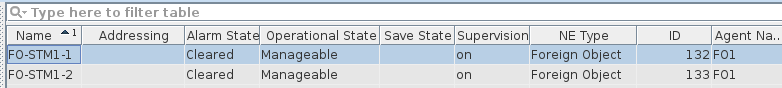
10. In the NEM Configurator, when selecting the an agent of type FO, the two new NEs of type FO are now listed:
11. Add the new elements (NEs of type FO) to the NP Domain.
12. Create three STM-1 optical sections:
• NE_80 to FO-STM1-1,
• FO-STM1-1 to FO-STM1-2,
• FO-STM1-2 to NE_82.
• To do so, open the “Section Management” dialog, click on “New Section”, select the appropriate “A End NE” and “Z End NE”, enter a “Name” for the section, set the cost if required, Select the “A End TP” and “Z End TP” from the list of available TPs, then click “Apply”. Repeat this for each of the three sections from the list above.
• This will result in the following three new entries in the section list:

• Note: alternatively you can also initiate this from the NEM Network Browser if you have already added the NEs to the map.
13. Open the Networking Package main window. Click the “Create a new Application” icon or select “File - New Application” from the menu.
• In the Application dialog, click the “Create a new transport entity” icon or select “Edit - New...” from the menu.
14. In the “New TE” dialog, select
• a End NE = NE_80, z End NE = N_82,
• Type=Trail,
• Layer=P12,
• a End TP: any available P12,
• z End TP: any available P12, then click “OK”.
15. Select the working path entry “Hole” of the new TE and click “Manual Routing...”
• Select the first P12 between local TP and Remote TP including the NE of type FO, then click “OK”.
• This will create the TEs for P12 and VC12 layers in the application.