
Create E-Tree with double Root and PE Dual Home
The following procedure describes the creation process for a sample E-Tree with a double Root and PE Dual Home after having passed the initial steps in section E-Tree creation wizard.
To create an E-Tree with a double root and PE Dual Home,
Proceed as follows:
1. Still in step 1 “General” of the wizard, select an appropriate service profile for the E-Tree VPLS.
• Click “Next >” to proceed to step 2 “Endpoints” of the wizard.
2. Click “+ Add Nodes”, then select the “Root” role.
• Enter the required VLAN ID for the E-Tree
• Select two (2) Root nodes from the list and click “Apply”.
• Set the Mode to “PE Dual Home”, select the required Primary Node; in this sample it is NE_80.
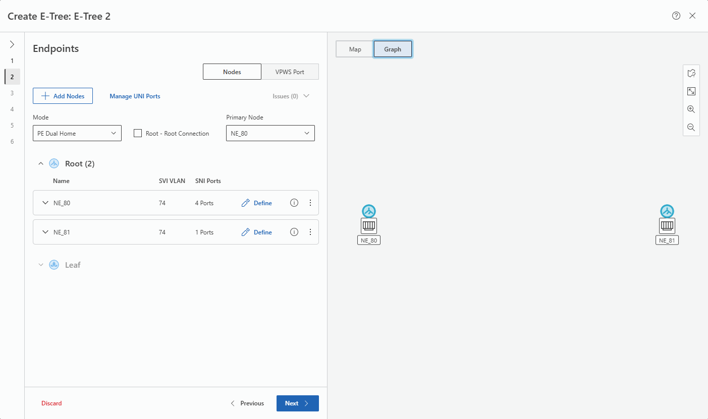
• The Root nodes will be listed under “Root (2)” and appear on the Graph:
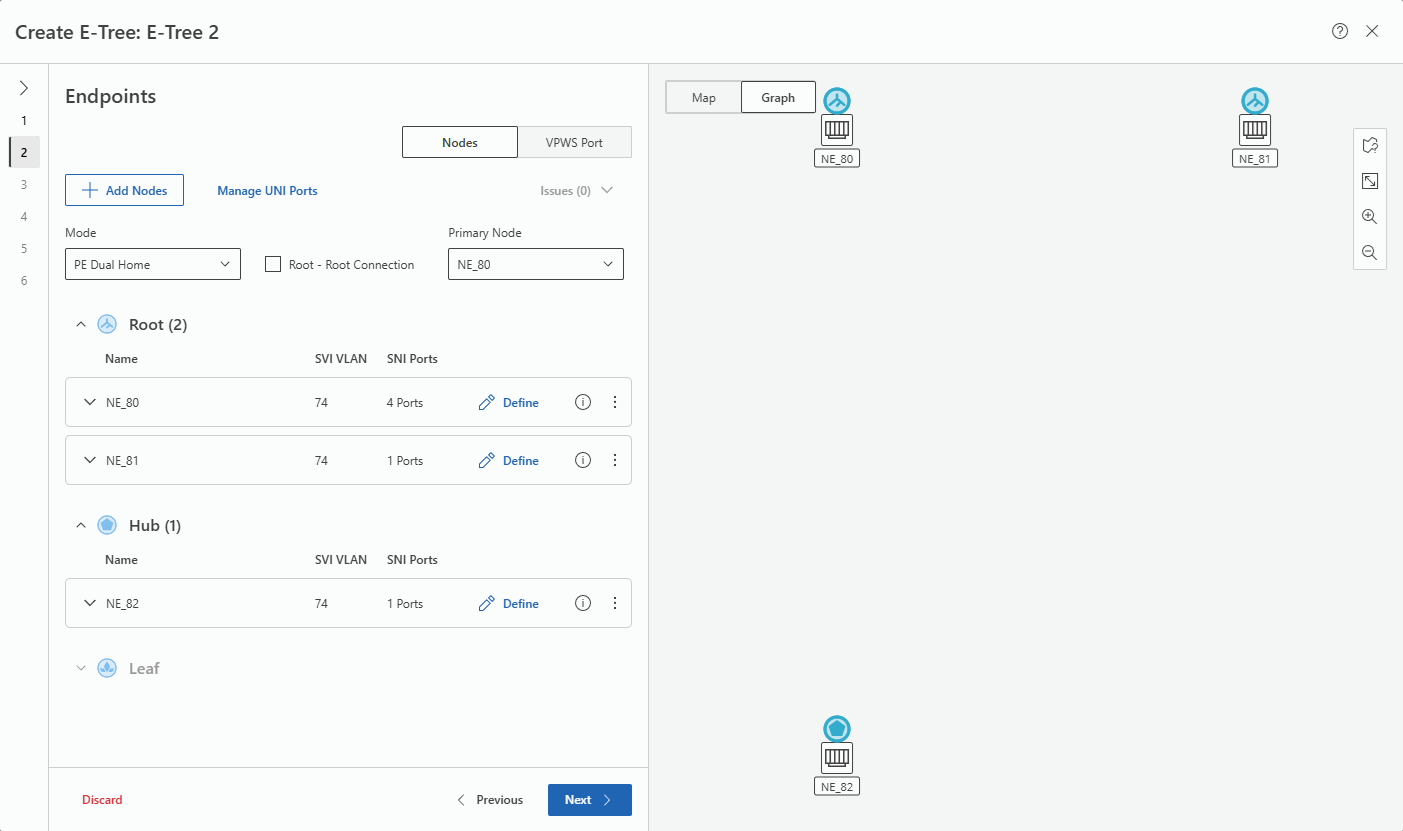
3. Click again “+ Add Nodes”, then select the “Hub” role.
• Select a single Hub node from the list and click “Apply”; the Hub node will be listed under “Hub (n)” and appear on the Graph:
4. Click again “+ Add Nodes”, then select the “Leaf” role.
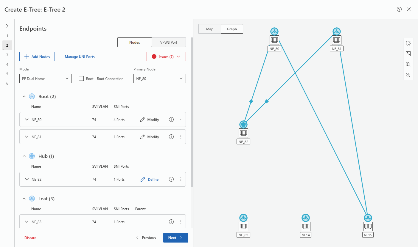
• Select three Leaf nodes from the list and click “Apply”; the Leaf nodes will be listed under “Leaf (n)” and appear on the Graph:
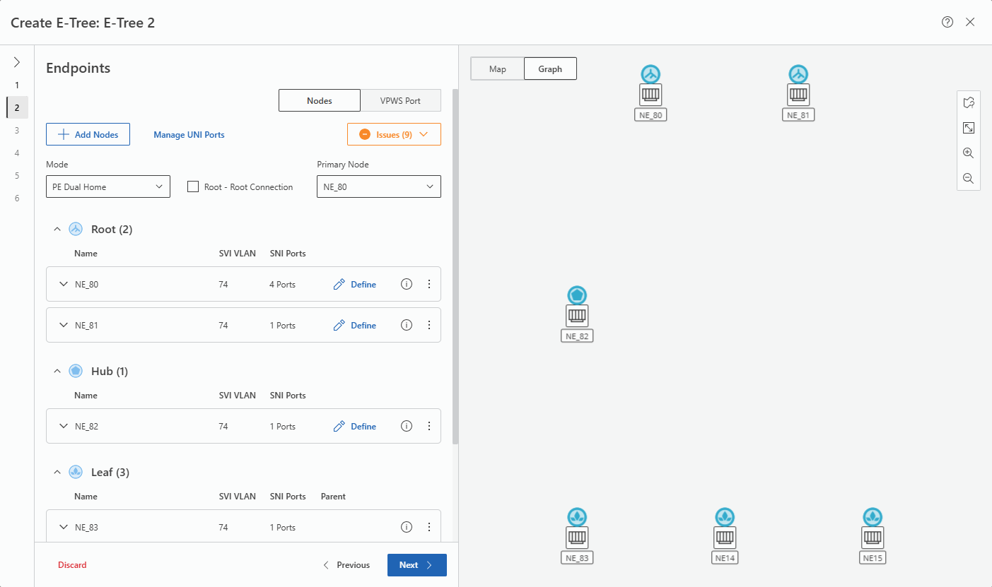
• In the map, click the “fit content to screen”  icon to adjust the graph to the map size.
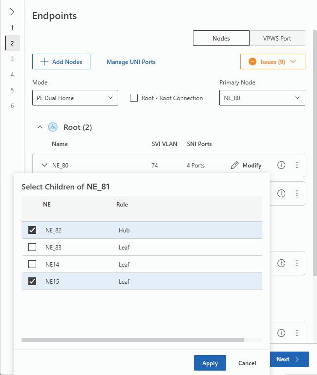
icon to adjust the graph to the map size.In the box for the first Root node, click on the  command to set the children of the Root node.
command to set the children of the Root node.• Select the Hub node and a Leaf node as children.
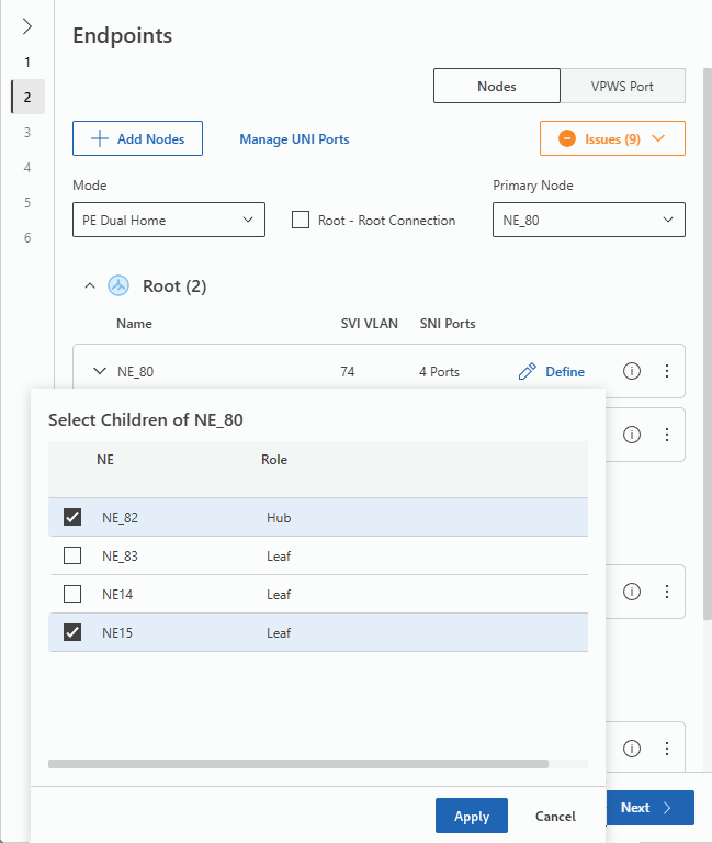
• Click “Apply”.
• In the box for the second Root node, click on the command to set the children of the Root node.
command to set the children of the Root node.• Select the Hub node and the same Leaf node as children as done for the first Root node.
• Click “Apply”.
• This will show the children to the two Root nodes on the Graph:
In the box for the Hub node, click on the command to set the children of the Hub node.
command to set the children of the Hub node.• Select the remaining two Leaf nodes as children.
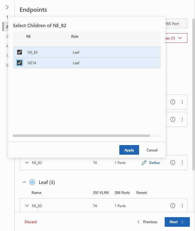
• Click “Apply”.
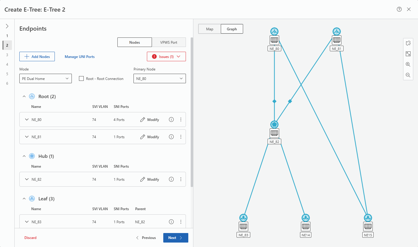
In the map, click the “fit content to screen” icon if required to adjust the graph to the map size if not yet done.
icon if required to adjust the graph to the map size if not yet done.• This will show the final graph for the sample E-Tree with double Root.
8. Click “Next >” to proceed to step 3 “Rate Limiter” of the wizard to configure the Rate Limiter if required and if supported by the service profile.
9. Click “Next >” to proceed to step 4 “Pseudo Wires” of the wizard to configure, confirm or modify the Pseudo Wires.
10. Click “Next >” to proceed to step 5 “Tunnels” of the wizard to route, select or confirm Tunnels. Missing or incomplete tunnels must be created/routed. This can be done by clicking “Route All Tunnels Automatcally” command or by creating a new tunnel where required. All Tunnels must be valid to be able to proceed.
11. Click “Next >” to proceed to step 6 “Summary” of the wizard to view a summary. Click on “Save” , then “Deploy”, or expand the Save command and select “Save & Deploy” to deploy the E-Tree VPLS.
12. Click “Finish” to close the wizard. With this the application will return to the MPLS map.
When back in the MPLS map, the new E-Tree VPLS is listed in the Entity Browser (left panel). Select the new E-Tree VPLS and click the  command in the ribbon or from the context menu. In the table of contents, select “E-Tree Graph” to view the graph for the E-Tree.
command in the ribbon or from the context menu. In the table of contents, select “E-Tree Graph” to view the graph for the E-Tree.Result: The E-Tree has been created and deployed to the network.
End of instruction